


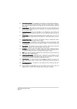


(3)
Use Channel Strings
.
Decide if you wish to store descriptive text for any of the channel
frequencies that will be programmed. If you do, use the mouse to ensure the box is checked.
If you do not wish to use this facility, use the mouse to ensure the box is empty.
Notes …
If the Use Channel Strings facility is selected, the maximum number of channel
frequencies that can be stored is reduced from 760 to 400.
Descriptive text is shown on the frequency list within this programme; it is not displayed
at the radio.
T6M Base Station User Guide
Page 41
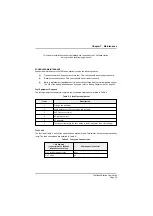
General Page
[Note that the status line at the bottom of the page displays help messages when the mouse pointer is placed
over a programmable option.]
Содержание T6M
Страница 1: ...T6M Base Station User Guide Handbook Part Number 31 360T6MBS...
Страница 12: ...Intentionally Blank T6M Base Station User Guide Page 12...
Страница 16: ...Intentionally Blank T6M Base Station User Guide Page 16...
Страница 48: ...Intentionally Blank T6M Base Station User Guide Page 48...
Страница 56: ...Intentionally Blank T6M Base Station User Guide Page 56...
Страница 58: ...Intentionally Blank T6M Base Station User Guide Page 58...
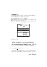
Страница 59: ...BT6MBS 01 Front and Rear Layout Figure 1...
Страница 60: ...BT6MBS 13 Rack Mounted Version Figure 2...
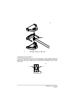
Страница 61: ...GA10642 Iss 1 Key to Front Panel Controls Figure 3 For description of controls see text in chapter 3...
Страница 62: ...BT6MBS 11 External Connection Diagram Figure 4...
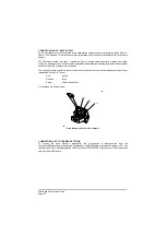
Страница 63: ...BT6MBS 10 Enclosure Securing Detail Figure 5...
Страница 64: ...Base Station Block Diagram Figure 6 GA10547 Iss 3...
Страница 65: ...Base Station Interconnection Diagram Figure 7 GA10548 Iss 3...
Страница 66: ...Base Station Layout Diagram Figure 8 GA10719 Iss 1...
Страница 69: ...Interface PCB Layout Diagram Figure 11 GA10751 Iss 1...
Страница 70: ...BT6MBS 12 1 Cable Termination at the N Type Connector Figure 12...