


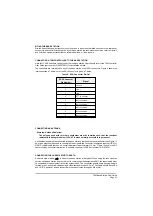


UNPACKING
When the base station is received from PAE, remove the packaging and check that the items listed in
Table 3 are included.
Table 3. Installation Materials
Item
Number
Description
Quantity
PAE
Part Number
1
Base station complete with enclosure
1
BT6MBS
2
Microphone terminated with 7-pin DIN plug
1
24-11030301
3
2 metres of mains cable terminated with a
3-pole socket (mates with AC input plug)
1
17-03000038S
4
15-way D-type plug (mates with Facilities
socket) comprising:
Plug connector
Cover
1
1
20-01150100
20D09150101
If ordered, a programming kit may be included. This kit, part number 70-T6MPMKIT, comprises:
q
CD containing the software.
q
Base station to PC connecting cable.
SETTING INTERNAL LINKS
Two internal links must be correctly set before the base station is used. Both links are factory set, but
may require checking if a replacement Interface module is fitted during the life of the base station. The
two links are:
q
Interface module JP1. This link determines whether received audio, or transmitted and received
audio, is monitored through the internal loudspeaker (see ‘Local Monitoring of Transmitted
Audio’ on page 11).
q
Interface module JP2. This link is set to correspond with the internal battery being fitted, or not
fitted.
When a base station is received from PAE, the links are normally set as per the user's requirements. If
there are any doubts, however, check the links as follows:
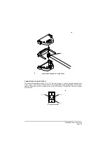
(1)
Refer to Figure 5 that shows the base station in its enclosure. Remove and retain the six M4
pan head screws and associated washers that secure the equipment within the enclosure.
(2)
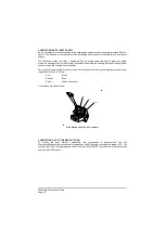
Slide the equipment forward out of the enclosure. Refer to Figure 8 and identify the Interface
PCB. Refer to Figure 11 and identify links JP1 and JP2.
(3)
Ensure the two links are set to the required positions.
(4)
Slide the equipment back into its enclosure. Refit the six M4 securing screws and washers.
T6M Base Station User Guide
Page 30
Содержание T6M
Страница 1: ...T6M Base Station User Guide Handbook Part Number 31 360T6MBS...
Страница 12: ...Intentionally Blank T6M Base Station User Guide Page 12...
Страница 16: ...Intentionally Blank T6M Base Station User Guide Page 16...
Страница 48: ...Intentionally Blank T6M Base Station User Guide Page 48...
Страница 56: ...Intentionally Blank T6M Base Station User Guide Page 56...
Страница 58: ...Intentionally Blank T6M Base Station User Guide Page 58...
Страница 59: ...BT6MBS 01 Front and Rear Layout Figure 1...
Страница 60: ...BT6MBS 13 Rack Mounted Version Figure 2...
Страница 61: ...GA10642 Iss 1 Key to Front Panel Controls Figure 3 For description of controls see text in chapter 3...
Страница 62: ...BT6MBS 11 External Connection Diagram Figure 4...
Страница 63: ...BT6MBS 10 Enclosure Securing Detail Figure 5...
Страница 64: ...Base Station Block Diagram Figure 6 GA10547 Iss 3...
Страница 65: ...Base Station Interconnection Diagram Figure 7 GA10548 Iss 3...
Страница 66: ...Base Station Layout Diagram Figure 8 GA10719 Iss 1...
Страница 69: ...Interface PCB Layout Diagram Figure 11 GA10751 Iss 1...
Страница 70: ...BT6MBS 12 1 Cable Termination at the N Type Connector Figure 12...