


14
Connecting the Uplink Lines
To connect the SMD2000-24E to E1 service:
1.
Configure the E1 uplinks.
No configuration is necessary for the SMD2000-24E to operate at default settings.
However, if you wish to run uplinks at settings other than the SMD2000-24E
defaults, configure the uplinks prior to connection. Parameter settings may be
changed using the Command Line Interface (CLI), Simple Network Management
Protocol (SNMP), or the web-based management system.
on page 15 lists the device defaults for the E1 uplinks.
on page 3 lists the user interface manuals.
2.
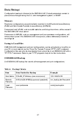
Plug your E1 cable into an RJ45 E1 uplink port on the SMD2000-24E faceplate. For
most applications, a straight-through E1 cable is required. A connection to Port 2 is
shown.
3.
Connect to the remote E1 equipment. The SMD2000-24E requires only one uplink
connection for operational purposes, although a second E1 uplink connection may
be desired for redundancy. Additionally, the two E1 uplink ports may be bonded
together for a single connection as long as the remote E1 equipment is loop
bonding capable. Refer to
Product to Product E1 Loop Bonding Compatibility
,
(Document Number COMP-A2-GK43) for a list of loop bonding capable products.
Using two E1 lines for one uplink connection nets twice the speed and data passing
capability of a single-line E1 connection. Additionally, use of a second E1 line
provides automatic backup should one of the lines experience problems or become
disabled.
A single line E1 uplink connection may be established between E1 Port 1 or E1
Port 2 and any standard E1 provider equipment.
4.
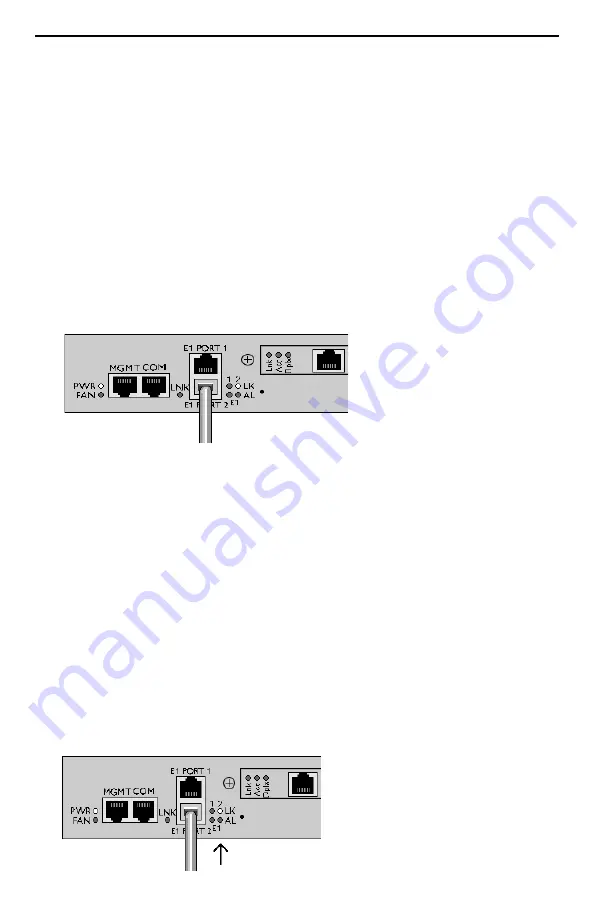
Verify Your Connections. The Port 1 Link (LK) LED flashing or pulsing green
indicates that a E1 Port 1 uplink connection has been established. The Port 2 Link
(LK) LED flashing or pulsing green indicates that a E1 Port 2 uplink connection has
been established.


