
NVX80 V1.07 Installation Quick Start
Important
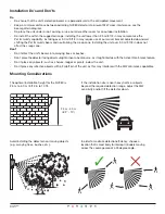
: Keep a 20 mm/0.80 in
clearance from the top of the unit’s
plastic casing to the ceiling or
object placed above the unit.
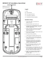
Legend
L – Level
W1 – Wall installation
W2 – Wall Tamper Installation
C1 – Corner-Mount Installation
C2 – Corner-Mount Tamper Installation
Installation Steps
1. Loosen the tamper screw found at the
bottom of the unit.
2. Separate the back cover from the unit.
3. Drill or punch out the appropriate knock-out holes
for either a wall or corner installation, refer to the
installation legend above.
4. Make sure to allow for 20 mm/0.80 in of space
between the top of the unit and a ceiling or
object found above it.
5. Mark your selected location using the back cover
of the unit as a template.
6. Drill holes into the wall surface.
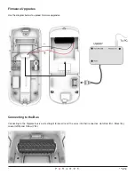
7. Thread the wires through the wire entry hole.
8. Secure the back cover of the unit to the wall
surface using mounting screws appropriate for
the specific installation.
9. Slide the front section of the unit into place
on the back cover of the unit. If the wires are
connected to electricity, then the power up
sequence will automatically start.
10. Ensure that the outer rim of the unit is tightly
joined, so that waterproof casing is not
compromised.
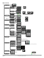
11. While the tamper screw at the bottom of the unit is
open, begin the power up process and access the
menus to change any sensitivity or other settings,
then press OK to save the altered settings.
12. Tightly close the tamper screw found at the
bottom of unit and put the detector into
operation mode.
For the complete manual visit www.paradox.com.
L
C1
C1
C1
W1
W1
W1
W2
C2
Wiring
Entry
Hole
C1
W2
C2
R+
B-
GRN YEL TMP NC1
C1
NO1 NC2 COM NC3
1
NVX80-EQ02
06/2013