1
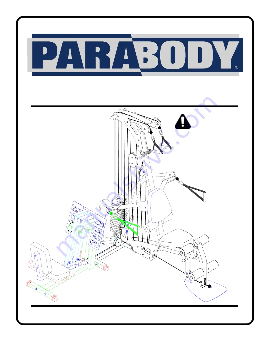
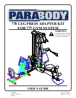
778 LEG PRESS ADAPTER KIT
FOR 777 GYM SYSTEM
CLASS HPART # 7031501REV. B
Version: 778101Revision: 02/28/01
USER’S GUIDE
WARNING:
Read and follow all directionsfor each step to insure properassembly of this product.
Страница 1: ...EG PRESS ADAPTER KIT FOR 777 GYM SYSTEM CLASS H PART 7031501 REV B Version 778101 Revision 02 28 01 USER S GUIDE WARNING Read and follow all directions for each step to insure proper assembly of this...
Страница 2: ...se the machine if found in this condition DO NOT attempt to fix Notify your authorized ParaBody dealer 7 Inspect cables and their connections before using machine Pay particular attention to the cable...
Страница 3: ...o assure its proper function 9 16 wrench Ratchet with 9 16 sockets Adjustable wrench Tape measure 3 NOTE BOLT LENGTH IS MEASURED FROM THE UNDERSIDE OFTHE HEAD OFTHE BOLT BOLT LENGTH RULER This product...
Страница 4: ...Length 90 inches 229 cm 7 6 Width 103 inches 262 cm 8 7 Height 84 inches 213 5 cm 7 1 Square 1 X 1 Length 90 inches 229 cm 7 6 Width 130 inches 330 cm 10 10 9 1 2 3 4 5 6 7 8 1 6 5 4 3 2 Dimensions In...
Страница 5: ...X 1 3 4 BOLT 3 8 X 3 BOLT 3 8 X 4 1 2 BOLT QTY 9 5 2 2 2 DESCRIPTION FRONT LEG PULLEY BRACKET WEIGHTSTACK CABLE LEG PRESS CABLE 3 1 2 PULLEY 2 COVER CAP KEY 7 8 9 10 11 NOTE The LEG PRESS ATTACHMENT...
Страница 6: ...PULLEY BRACKET 2 using one 3 8 X 1 3 4 BOLT 9 and one 3 8 LOCK NUT 8 Note Loop the 120 CABLE around the PULLEY prior to assembling the PULLEY BRACKET Screw the long threaded end of the new WEIGHT STA...
Страница 7: ...EP 3 Slide two 2 SQ COVER CAPS 6 over the FRONT LEG 1 as shown in FIGURE 3 1 6 7 FIGURE 4 STEP 4 Remove the 3 8 X 3 3 4 BOLT and 3 8 LOCK NUT from the BASE PLATE as shown in FIGURE 4 3 8 LOCKNUT 3 8 X...
Страница 8: ...TEP 5 SECURELY assemble the FRONT LEG 1 to the 777 Gym System using two 3 8 X 4 1 2 BOLTS 11 five 3 8 WASHERS 7 one previously removed 3 8 LOCK NUT and one 3 8 LOCK NUT 8 as shown in FIGURE 5 1 8 7 11...
Страница 9: ...E 6 NOTE The pulley will be used in STEP 9 3 1 2 PULLEY 2 WHEEL 3 8 X 4 1 2 BOLT SPACER FIGURE 7 STEP 7 Assemble the LEG PRESS CABLE 4 to the ADJUSTMENT TUBE on the 100 LEG PRESS using the existing pr...
Страница 10: ...10 FIGURE 8 STEP 8 Securely fasten the 100 LEG PRESS to the FRONT LEG 1 using two 3 8 X 3 BOLTS 10 four 3 8 WASHERS 7 and two 3 8 LOCK NUTS 8 as shown in FIGURE 8 4 7 1 8 100 LEG PRESS 10 3 8 X 3...
Страница 11: ...RELY assemble the previously removed 3 1 2 PULLEY to the FRONT LEG 1 using one 3 8 X 1 3 4 BOLT 9 and one 3 8 LOCK NUT 8 See FIGURE 9 NOTE Loop the LEG PRESS CABLE around the pulley prior to assemblin...
Страница 12: ...12 FIGURE 10 STEP 10 Screw the threaded end of LEG PRESS CABLE 4 to the PULLEY BRACKET 2 as shown in FIGURE 10 4 2...
Страница 13: ...t of tension in the cables push the HEAD PLATE down insert the WEIGHT SELECTOR PIN adjust the 100 LEG PRESS into the last adjustment hole so the LEG PRESS is spread apart and perform several repititio...