1
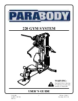
220 GYM SYSTEM
CLASS HPART # 7017301REV. G
Revision: 09/13/01
USER’S GUIDE
WARNING:
Read and follow all directionsfor each step to insure properassembly of this product.
Version: 220101
Страница 1: ...1 220 GYM SYSTEM CLASS H PART 7017301 REV G Revision 09 13 01 USER S GUIDE WARNING Read and follow all directions for each step to insure proper assembly of this product Version 220101 ...
Страница 2: ...use the machine if found in this condition DO NOT attempt to fix Notify your authorized ParaBody dealer 7 Inspect cables and their connections before using machine Pay particular attention to the cable ends DO NOT attempt to fix Notify your authorized ParaBody dealer before use and have repairs made by an authorized service technician 8 Make sure all spring loaded pull pins are fully engaged in th...
Страница 3: ...tchet with 3 4 and 9 16 sockets 5 32 Allen wrench Adjustable wrench Tape measure 3 NOTE BOLT LENGTH IS MEASURED FROM THE UNDERSIDE OFTHE HEAD OFTHE BOLT BOLT LENGTH RULER This product must be assembled on a flat level surface to assure its proper function DO NOT securely tighten any frame connections until the entire frame has been assembled unless otherwise stated Bolt Length Ruler 0 1 2 3 4 5 6 ...
Страница 4: ...th 82 inches 208 5 cm 6 10 Width 71 inches 180 5 cm 5 11 Height 83 inches 211 cm 6 11 1 Square 1 X 1 4 Length 82 inches 208 5 cm 6 10 Width 108 inches 180 5 cm 9 0 9 1 2 3 4 5 6 7 8 1 7 6 5 4 3 2 Dimensions Including Leg Press optional ...
Страница 5: ...T WASHER 3 4 FLAT WASHER 3 4 PLASTIC WASHER 1 2 FLANGE BEARING 3 8 X 9 16 FLANGE SPACER 3 8 X 1 1 16 FLANGE SPACER 3 8 X 1 LG SPACER 3 8 X 1 3 16 LG SPACER WEIGHT STACK SPACER WEIGHT STACK CUSHION 5 16 X 2 ROLL PIN ASSEMBLY SHAFT COLLAR 3 8 LOCKING SPRING PIN 3 8 SPRING PIN WEIGHT SELECTOR PIN 3 PRONG KNOB ADJUSTABLE GLIDE STARLOCK COLLAR RH CAP 1 2 RHCAP HOLDER WASHER SNAP LINK PARAGLIDES QTY 8 E...
Страница 6: ... x 3 BOLT 29 and one 3 8 LOCKNUT 34 1 34 30 2 62 3 8 X 3 3 4 29 41 34 3 LOOSELY assemble two BASE PLATES 3 to the FRAME 1 and BASE 2 using four 3 8 X 3 3 4 BOLTS 30 and four 3 8 LOCK NUTS 34 See FIGURE 1 Insert two 3 8 x 9 16 FLANGE SPACERS 41 into the upper holes in the FRAME 1 as shown in figure 1 ...
Страница 7: ...o WEIGHT PLATE BUSHINGS 23 into each of the fifteen WEIGHT PLATES 22 as shown in FIGURE 2 STEP 2 Slide the WEIGHT PLATE SHAFT 18 thru the hole in the HEAD PLATE 19 and lock in place using one E RING 60 as shown in FIGURE 3 23 22 19 60 18 ...
Страница 8: ...ch GUIDE ROD 16 FIGURE 4 2 46 38 16 48 45 Slide the following items in order down each GUIDE ROD 16 one WEIGHT STACK SPACER 45 one 3 4 FLAT WASHER 38 and one WEIGHT STACK CUSHION 46 STEP 5 Carefully slide the RIGHT 5 and LEFT 4 BOOM PLATES onto the GUIDE RODS 16 as shown in FIGURE 5 and loosely assembly BOOM PLATES 5 4 to frame 1 using two 3 8 x 3 3 4 BOLTS 30 and two 3 8 LOCK NUT 34 CAUTION MUST ...
Страница 9: ...M 8 FIGURE 7 7 36 34 47 6 Once in place secure and tighten the LEFT PRESS HANDLE 7 to PRESS ARM 8 using one 3 8 WASHER 36 and one 3 8 LOCK NUT 34 SLOT 0 1 2 3 4 5 6 1 2 1 2 1 2 1 2 1 2 1 2 NOTE Place PRESS ARM 8 upside down on floor as shown to complete this step 47 Insert two 1 2 FLANGE BEARINGS 40 into the LEFT PRESS HANDLE 7 as shown in FIGURE 6 Repeat STEP 6 for the RIGHT PRESS ARM HANDLE 6 Re...
Страница 10: ... two 3 8 X 3 BOLTS 29 four 3 8 FLAT WASHERS 36 two 3 8 LOCK NUTS 34 Insert and tighten two 3 8 LOCKING SPRING PINS 49 into PRESS HANDLES 6 7 3 8 X 3 10 Lock PRESS ARMS 6 7 into place using 3 8 LOCKING SPRING PINS 49 Locking Spring Pin To disengage LOCKING SPRING PINS 49 pull out and twist 1 4 turn ...
Страница 11: ...f the FRAME 1 using 1 2 X 8 BOLT 33 two 1 2 FLAT WASHERS 37 and 1 2 LOW HT LOCK NUT 35 IMPORTANT DO NOT TIGHTEN YET SECURELY TIGHTEN ALL FRAME CONNECTION BEFORE PROCEEDING TO NEXT STEP 33 37 35 48 9 1 1 2 X 8 DO NOT TIGHTEN SECURELY TIGHTEN SECURELY TIGHTEN top of both SHAFT COLLARS 48 flush to bottom of both BOOM PLATES 4 5 ...
Страница 12: ...wo 3 8 X 2 3 4 BOLTS 28 and two 3 8 WASHERS 36 as shown FIGURE 10 Securely assemble one SEAT PAD 13 to the FRAME 1 using two 3 8 X 2 3 4 BOLTS 28 and two 3 8 WASHERS 36 as shown Gently insert SEAT ADJUSTMENT 10 into tube located on FRAME 1 DO NOT FORCE THE SEATADJUSTMENT IN THIS MAY CAUSE THE PARAGLIDES TO TEAR Apply WEIGHT STACK LABELS 61 to WEIGHTS 22 and HEAD PLATE 19 as shown in FIGURE 10 Begi...
Страница 13: ... to the FRAME 1 using one 1 2 X 4 BOLT 32 two RH WASHERS 56 and one 1 2 LOW HT LOCK NUT 35 Assemble two RH CAPS 55 to the 1 2 RH WASHERS 56 as shown in FIGURE 11 Route LAT CABLE 20 and LOW CABLE 21 as shown in FIGURE 12 40 32 20 55 STEP 12 21 1 11 56 35 FIGURE 12 1 2 X 4 0 1 2 3 4 5 6 1 2 1 2 1 2 1 2 1 2 1 2 13 ...
Страница 14: ...ILLUSTRATION A NOTE IF YOU PURCHASEDALEG PRESS PLEASE REFER TO THE CABLE ROUTING INSTRUCTIONS INCLUDED WITH THE LEG PRESS KIT 14 ILLUSTRATION A used as cable routing reference for steps 13 16 ...
Страница 15: ...ULLEY 24 into PRIMARY PIVOT 9 upper hole using one 3 8 X 8 BOLT 31 two 3 8 FLAT WASHERS 36 two 3 8 X 1 3 16 SPACERS 44 and one 3 8 LOCK NUT 34 and tighten securely Assemble two 3 1 2 PULLEYS 24 into FRAME 1 using two 3 8 X 3 3 4 BOLTS 30 four 3 8 X 1 1 16 FLANGE SPACERS 42 and two 3 8 LOCK NUTS 34 and tighten securely 9 34 36 24 42 44 31 30 1 3 8 X 3 3 4 3 8 X 8 ...
Страница 16: ...ne 3 1 2 PULLEY 24 into the PRIMARY PIVOT 9 lower hole using one 3 8 X 8 BOLT 31 two 3 8 FLAT WASHERS 36 two 3 8 X 1 3 16 SPACERS 44 and one 3 8 LOCK NUT 34 and tighten securely Assemble two 3 1 2 PULLEYS 24 between the left and right BOOM PLATES 4 and 5 using two 3 8 X 3 3 4 BOLTS 30 four 3 8 X 1 SPACERS 43 and two 3 8 LOCK NUTS 34 Loosely assemble one 3 1 2 PULLEY 24 between PULLEY PLATES 12 usi...
Страница 17: ...3 4 5 6 1 2 1 2 1 2 1 2 1 2 1 2 FIGURE 15 20 Slip ring of WEIGHT SELECTOR PIN 51 down WEIGHT STACK SHAFT 18 and insert pin into one of the weights 51 18 SECURELY TIGHTEN JAM NUT DO NOT OVERTIGHTEN 35 Securely tighten 1 2 LOCK NUT 35 on PRIMARY PIVOT of PRESS ARM 9 IMPORTANT DO NOT OVERTIGHTEN PRESSARM SHOULD ROTATE FREELY ...
Страница 18: ...the ball end of the LOW CABLE 21 and one 3 1 2 PULLEY 24 to the LEG PEDESTAL 11 using two 3 8 X 3 3 4 BOLTS 30 two 3 8 X 1 1 16 FLANGE SPACERS 42 two 3 8 WASHERS 36 and two 3 8 LOCKNUTS 34 NOTE The LEG CABLE 21 should be routed over the retaining bolt as shown in FIGURE 16 Securely assemble one 3 1 2 PULLEY 24 to the FRAME 1 using one 3 8 X 3 BOLTS 29 and one 3 8 LOCKNUT 34 NOTE The LEG CABLE 21 s...
Страница 19: ...osely assemble one 3 1 2 PULLEY 24 between the PULLEY PLATES 12 using one 3 8 X 1 3 4 BOLT 27 and one 3 8 LOCK NUT 34 Assemble one 3 1 2 PULLEY 24 between BASE PLATES 3 using one 3 8 X 3 3 4 BOLT 30 two 3 8 X 1 SPACERS 43 one 3 8 LOCK NUT 34 and tighten securely Tighten both 3 1 2 PULLEYS 24 located on PULLEY PLATES 12 34 24 30 27 43 3 12 FIGURE 17 3 8 X 3 3 4 3 8 X 1 3 4 36 19 0 1 2 3 4 5 6 1 2 1...
Страница 20: ...RS 54 as shown in FIGURE 18 STEP 18 Attach two 4 X 7 ROLLER PADS 15 to the SEAT ADJUST 10 using one 3 4 X 1 TUBE 14 two PLASTIC WASHERS 39 and two 3 4 STARLOCK COLLARS 54 as shown in FIGURE 18 Attach two 4 X 7 ROLLER PADS 15 to the FRAME 1 using one 3 4 X 17 TUBE 14 and two 3 4 STARLOCK COLLARS 54 as shown in FIGURE 18 54 FIGURE 18 15 14 39 10 1 11 ...
Страница 21: ... PLATE 22 or if there is excess slack in the cable system adjust the threaded end of the LAT CABLE 20 and ADJUSTABLE GLIDE 53 accordingly and retighten the jam nuts See figure 19 For maximum performance the HEAD PLATE 19 should just barely sit on the top WEIGHT PLATE 22 Attach the ERGO BAR 17 to the ball end of LAT CABLE 20 using one SNAP LINK 57 as shown in FIGURE 19 Attach the ANKLE STRAP 25 to ...
Страница 22: ...ustomer service representative at 800 328 9714 Inspect equipment daily Tighten all loose connections are replace worn parts immediately Failure to do so may result in serious injury Lubricate guide rods with a teflon based or equivalent lubricant on a regular basis Thank you for purchasing the ParaBody 220 Gym System Please note PLEASE RECORD THE INFORMATION REQUESTED BELOW IN THE EVENT YOU MAY NE...
Страница 23: ...ive charges for returning parts to ParaBody and c all necessary or incidental costs related to installation of the replacement parts 6 SHIPPING If shipping by the Owners is deemed necessary in sole discretion of ParaBody parts should be shipped in their original carton or equivalent packaging fully insured with shipping charges prepaid ParaBody will not assume any responsibility for any loss or da...
Страница 24: ... 64 66 99 LIFE FITNESS CONSUMER DIVISION 14150 Sunfish Lake Blvd Ramsey Minnesota 55303 U S A Tel 763 323 4500 Fax 763 323 4797 800 328 9714 Toll free within the U S and Canada www parabody com 24 Life Fitness EUROPE GmbH Siemensstrasse 3 85716 Unterschleissheim Germany Phone 089 31 77 51 0 Fax 089 31 77 51 99 Life Fitness Italia S R L Via Elvas 92 39042 Bressanone Italy Phone 39 472 835 470 Fax 3...