


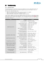


BA_PH_680-100_EN_08-22.docx
61
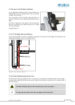
15.13
Swivel-Away Device for the Cross Slide
For some operations it may be necessary to remove the cross slide. For this purpose, the optional swivel-away
device available under Art. No. 4770 is a useful aid.
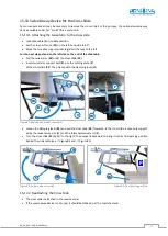
15.13.1
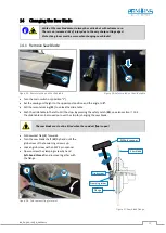
Attaching the swivel arm to the cross slide
•
Lock slide table (
5
) in middle position.
•
Set the cross-cut fence (
13
) on the left-hand side to 90°.
•
Move the movable support widening (
V
) all the way to the left.
For the next steps, stand on the left side to the end of the slide table.
•
Pull the swivel arm (
W
) under the cross slide (
22
).
•
Insert swivel arm support bolt (
B
) into the holding plate (
P
)
of the cross slide (
22
). Then clamp with the clamping lever (
H
).
Figure 83: Position and mount swivel arm
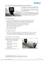
•
Loosen the clamping lever (
24
) and pull the cross slide (
22
) forwards
→
The cross slide is now only support-
ed by the swivel away arm (W) and the telescopic swivel arm (
S
).
•
Turn the cross slide (
22
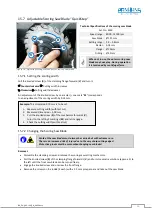
) by 90° to the right. Then swivel it backward to bring it into its final parking position
behind the slide table (see
Figure 84 and
Figure 84: Swivel away cross slide
Figure 85: Final parking position
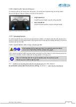
15.13.2
Reattaching the Cross Slide
•
The cross slide is attached in the reverse order.
•
If the swivel-away device is not used, it should be folded up at the machine stand.
24
13
V
B
W
22
5
W
B
P
H
S
H
W
Q
W
P