


PVIQ™ CONNECTIVITY SYSTEM USER MANUAL V 1.0
126
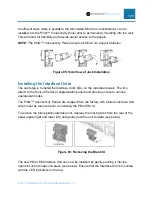
The “In” Expansion Port receives an EPC from either the PM or another EM.
Connecting the PM to the EM
Connect the PM to the first EM in the chain by attaching one end of the supplied
Expansion Port Cable (EPC) to the “Out” Expansion Port on the PM. Then attach the far
end of the EPC to the “In” Expansion Port of the first EM in the chain. The EPC will have
a positive latch when inserting into the Expansion Ports. To remove the EPC, depress
the locking tab on the EPC before removing it from the Expansion Port.
NOTE:
Ensure that the EPC is not bent or stretched to the point of stress.
Daisy Chaining EMs
To connect one EM to the next EM in the chain, attach one end of the supplied EPC to
the “Out” Expansion Port on the EM. Then attach the far end of the EPC to the “In”
Expansion Port of the next EM in the chain (see below). Up to 4 EMs may be daisy
chained to a single PM.
NOTE: Ensure that the EPC is not stretched or stressed in any way, especially when
using cable managers.
Connecting Multiple PMs
Multiple PMs may be daisy chained together, providing management access of
additional panels through a single LAN connection. Using this method, up to 30 PMs
can be controlled by a single LAN port.
Begin by attaching the shielded RJ45 cable (supplied) to either of the LAN connectors
on the back of the PM. Then, attach the far end of the cable to either of the LAN
connectors on the next PM in the chain.
Repeat this procedure for as many PMs as required (up to 30).
NOTE: Either LAN connector functions as either an “In” or an “Out” connection. Panduit
recommends establishing a standard convention for easier traceability. For example,
use the right connector as the “In” (closest to the network connection) connection and
the left connector as the “Out” connection.
NOTE: In order to avoid a “looping” error condition, ensure that the last PM in the chain
has one Ethernet port unconnected.
Connection Diagram
The figure below shows all of the connections described in this section. The table below
defines each of the connections.


