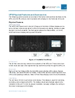
background image


SMARTZONE UPS USER MANUAL 


25 


system. The following  table provides the battery cartridge set part numbers that must be 
used with the specific  EBP part numbers. 

EBP Unit SKU 

Battery Cartridge Set SKU 

UVP240 

UVD240 

UVP480 

UVD480 


Maintenance Bypass Switch (UMB20K) 

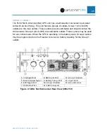
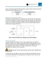
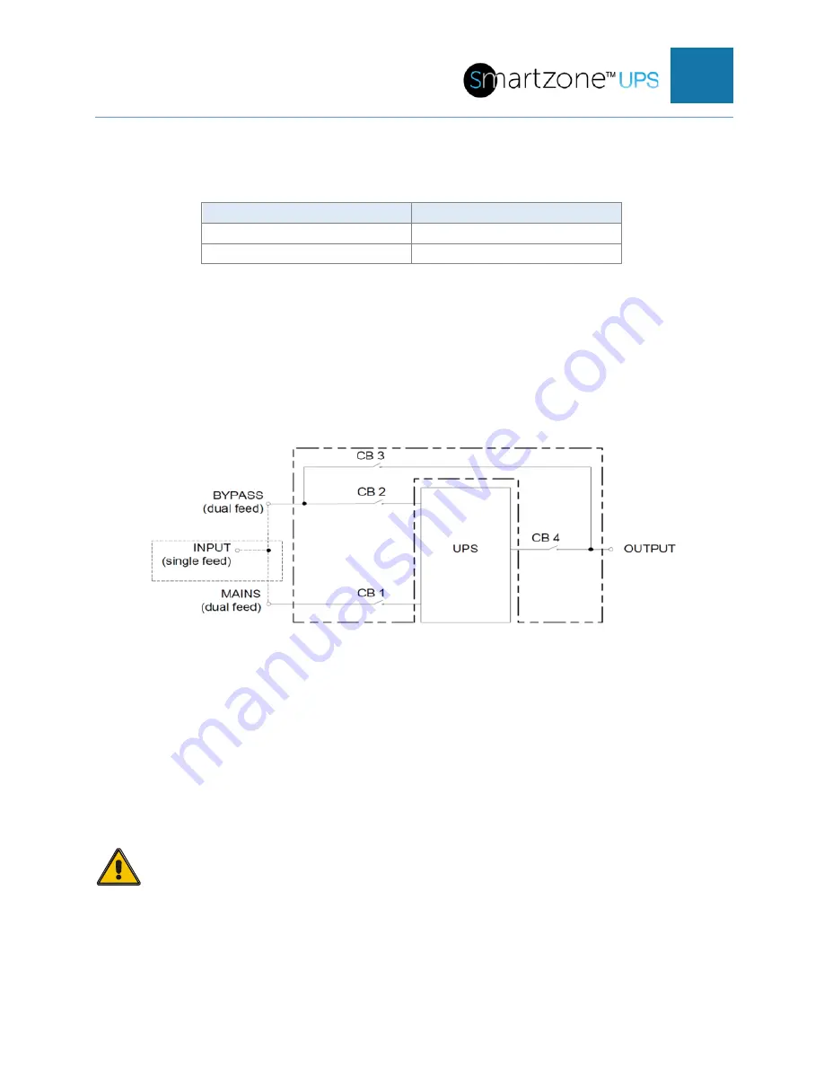
The Maintenance Bypass Switch is an optional 3 RU unit that allows the 3-phase UPS 
unit to be removed from the system without powering down the load. The UPS has two 
sensor ports. The MAINT port allows the UPS to monitor the Maintenance Switch lock 
(on CB  3). The OUTPUT port allows  the UPS  to monitor the output breaker (CB 4) in 
the Maintenance Bypass Switch unit. 


Figure 8: High-level Maintenance Bypass Switch Block Diagram 


Network Card (UNCP01) 

The network card comes installed in the “N” type model UPS  units (ex. U05N11V, 
U10N12V, U20N32V, etc.). Refer to the SmartZone UPS  Network Management Card 
User Manual for monitoring and controlling the UPS through the Network card. The “S” 
type model UPS units (ex. U05S11V, U10S12V, U20S32V,  etc.) may  be field 
upgradable with a network card or a relay card. 


CAUTION

! DO NOT TOUCH THE NETWORK CARD WITHOUT PROPER ESD 

PROTECTION. 

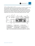
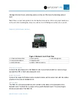
To install  or remove the Network card, remove and retain the two #0 Phillips  screws in 
the mounting holes labeled  7 in the below figure. If no network card is in the unit, the 

Содержание smartzone 10-20KVA

Страница 1: ...User Manual V3 2 Uninterruptible Power Supply 5 10KVA SINGLE PHASE 10 20KVA 3 PHASE...

Страница 2: ...e UPS on Main Input Power 31 Cold Starting the UPS Start the UPS on Battery 31 Starting a 3 Phase UPS with an Optional Maintenance Bypass Switch Unit 31 Switching to the Internal Bypass State 31 Switc...

Страница 3: ...LEDs 89 Appendix B Troubleshooting 97 Appendix C State Transitions Based on External Events 99 Appendix D Maintenance and Storage 101 Maintenance 101 Storage Transportation 101 Appendix E Configuratio...

Страница 4: ...mote network monitoring control and configuration The UPS may be optionally ordered without a network card Additionally a Network Card or a Dry Contact Relay Card may be ordered as accessories These U...

Страница 5: ...atteries are fully charged with out over voltage o 3rd stage float voltage charging to ensure the battery stays charged to the optimal level Ease of Use User Friendly Color Display with Color Status L...

Страница 6: ...tions The output is connected to loads via outlets or hardwire connections on the UPS The load may be powered from the input source or the battery The UPS power switching circuitry may be isolated fro...

Страница 7: ...harging input relay will open The bypass relay will remain opened The output relay will remain closed The battery will start providing the DC power to the DC to AC inverter continuing to provide unint...

Страница 8: ...he DC power to the DC to AC inverter continuing to provide uninterrupted AC power to the load The UPS is now in the Battery state While the UPS is operating in ECO mode if the input power has any othe...

Страница 9: ...he UPS is operating in CF mode if the input power is lost or has any other anomalies that are outside of the set ranges The batteries will stop charging input relay will open The bypass relay will rem...

Страница 10: ...relays open and the bypass relay closes assuming the input is not outside of the input bypass range continuing to provide unconditioned AC power to the load The UPS is now in the Bypass state with no...

Страница 11: ...xpired If an internal or external event occurs while operating in the CF state the UPS will automatically transition to battery bypass fault or battery test state depending on the event Gen State The...

Страница 12: ...erform periodic maintenance on the UPS The MBS unit will electrically disconnect the UPS from the system In the Maintenance Bypass state the source power is provided to the load with no power conditio...

Страница 13: ...ning the battery test after the batteryhas been fullycharged If Battery low EOD alarm is already present when the battery test is initiated the UPS will not start the battery test System Configuration...

Страница 14: ...ables must be the same type and same length This helps to facilitate load sharing and zero crossing alignment between the UPS units when operating in Parallel Mode Parallel Mode Setup and Startup Each...

Страница 15: ...rallel ID is unique for each UPS unit in the Parallel mode system After all UPS units in the Parallel mode system are configured power OFF all the UPS units in the system Connect the outputs of all th...

Страница 16: ...to 20kVA Front Panel Air Flow Vents The air flow vents are very critical to the operation of the UPS unit These vents must remain clean and clear of all objects that may restrict the air flow through...

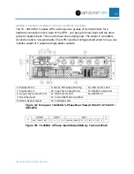
Страница 17: ...l be wired to a remote normally closed dry contact to provide a short for normal operation The remote dry contact could be opened to command the UPS to shut down in an emergency The 10 20kVA 3 phase U...

Страница 18: ...r BATTERYCONNECTOR All units have an External Battery Pack EBP power connection to connect to an external battery pack labeled 120Vdc or 240Vdc Each UPS Model has been calibrated to a specific EBP and...

Страница 19: ...UMB20K Output Breaker This port should be unconnected when no external Maintenance Bypass Switch is present in the system and should be connected to the OUTPUT port on the MBS unit when the MBS unit...

Страница 20: ...SMARTZONE UPS USER MANUAL 19 is assumed that all EBP units connected to the same system are in the same environmental conditions If this cable is not connected an alarm will be triggered...

Страница 21: ...loads Group 2 2x L6 30R are switchable outlets These outlets may be used for non critical loads When the UPS is operating in the battery state Group 2 outlets may be programmed to turn off earlier to...

Страница 22: ...L6 30R are switchable outlets These outlets may be used for non critical loads When the UPS is operating in the battery state Group 2 outlets may be programmed to turn off earlier to conserve battery...

Страница 23: ...loads Group 3 2x C 19 with a 16A output breaker are switchable outlets These outlets may be used for non critical loads When the UPS is operating in the battery state Group 2 and 3 outlets may be pro...

Страница 24: ...and is non switchable The UPS could be configured and wired to have one 3 phase output or 3 separate single phase outputs 4 Parallel Port 1 9 Maint BPS Output Brk Sig 14 USB Comms Port 5 Parallel Port...

Страница 25: ...to extend the runtime of the UPS when operating in the battery state The 5 10kVA single phase UPS units support up to five EBP units The 10 20kVA 3 phase UPS units support up to eight EBP units Addit...

Страница 26: ...UPS to monitor the output breaker CB 4 in the Maintenance Bypass Switch unit Figure 8 High level Maintenance Bypass Switch Block Diagram Network Card UNCP01 The network card comes installed in the N...

Страница 27: ...Status LEDs 7 Mountingholes 2 Sensor Connection 5 Reset button 3 MAC ID Label 6 Micro USB Connection Ethernet Connection Connect the ethernet port on the Network card to an ethernet switch or router u...

Страница 28: ...on the duration of the button press Reset the NMC when it does not respond Hold the reset button for 2 seconds and release when green LED starts flashing This will cause a reset of the NMC controller...

Страница 29: ...ty power fails Pin 1 to Pin 3 would change from NC Normal Closed to Open 4 AC fail Close When the input utility power fails Pin 1 to Pin 4 would change from NO Normal Opened to Close 5 Batt low Open W...

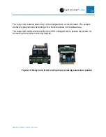
Страница 30: ...mon lead The outputs are factory programmed according to the functions listed in the table above The relay card must be removed from the UPS intelligent slot to access the screws for connecting the re...

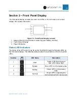
Страница 31: ...creen Display 3 Power ON Button Status LED Indicators The status of the UPS system may be quickly identified through the following LEDs on the front panel display The following table provides the desc...

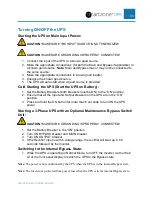
Страница 32: ...2 Ensure that all the Input and Output breakers on the UPS are in the ON position 3 Press and hold the ON button for more than 6 seconds to turn ON the UPS power Starting a 3 Phase UPS with an Option...

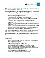
Страница 33: ...om the system and the MBS source is supplying power to the load through the MAINTENANCE breaker Note Wait for about 30 minutes for the internal DC bus capacitors to be completelydischarged before open...

Страница 34: ...t to the UPS unit 3 Switch OFF from up to down the BYPASS breaker on the MBS If there is no MBS then the breaker must be switched OFF at the power distribution panel feeding the bypass input of the UP...

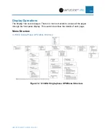
Страница 35: ...ay has several pages There is a menu structure to access all the pages through the front panel display This section describes the details of each page Menu Structure 5 10kVA Single Phase UPS Menu Stru...

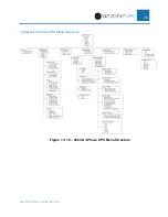
Страница 36: ...SMARTZONE UPS USER MANUAL 35 10 20kVA 3 Phase UPS Menu Structure Figure 13 10 20kVA 3 Phase UPS Menu Structure...

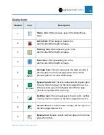
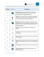
Страница 37: ...circuitry it will turn green on the home page when active When pressed goes to the Input Status page 6 BYPASS Bypass Input Icon This icon represents the bypass input circuitry It will turn green on t...

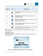
Страница 38: ...ery charge status Each incremental 25 bar is solid ON when charged or will blink ON and OFF when charging When pressed goes to the Battery Status page 13 Next Icon When pressed goes to next page in th...

Страница 39: ...e Menu page 22 Common Menu Page Icon When pressed goes to the Common Menu page 23 About Page Icon When pressed goes to the About page Provides information about the UPS unit Note The icons on the fron...

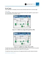
Страница 40: ...user needs for a quick view of the operating status of the UPS system Figure 15 5 10kVA Home Page EU Single Phase UPS Figure 16 10 20kVA Home Page 3 Phase UPS The dark blue banner along the top of th...

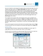
Страница 41: ...remainder of the page provides a block diagram of the system highlighting the current UPS working state The examples in Figure 15 and Figure 16 show the UPS in Normal mode working in the Normal state...

Страница 42: ...magnifying glass Status Menu page right left arrows Alarm Menu page bell Settings Menu page gear wheel Maintenance Menu page hand tools Common Menu page hand touch point or the About page question mar...

Страница 43: ...e depending on operations used to get to this page through the Status Menu page or through the Home page Bypass Input Status Page This page provides detailed bypass input measurements this page is sup...

Страница 44: ...over arrow to return to the previous page the Status Menu page or Home Page depending on operations used to get to this page Figure 22 Output Status Page 2 3 Phase UPS For the single phase UPS units...

Страница 45: ...ge Single Phase UPS This page contains the measured positive and negative bus voltage internal in the UPS and the measured ambient temperature at the input of the UPS The normal range of this DC bus i...

Страница 46: ...S connected in the system or there is an MBS in the system and the MBS is configured so the UPS is providing power to the load When the MBS breaker is closed it means there is an MBS in the system and...

Страница 47: ...ess the up and over arrow to return to the Status Menu page Figure 26 Status Information Page 3 3 Phase UPS The third page contains the Generator Access status The Generator Access point is sensed thr...

Страница 48: ...tery status and ambient temperature in the first connected EBP unit Note The voltage and current are shown for the positive batteryand the negative battery as described in Section 1 System Overview of...

Страница 49: ...rrow to go to the previous Battery Status page Press the up and over arrow to return to the previous page the Status Menu page or Home Page depending on operations used to get to this page Alarm Pages...

Страница 50: ...d by the red critical alarm icons and by yellow warning alarm icons Each entry also includes an alert code a short description and the location where the error occurred When the alert is cleared it wi...

Страница 51: ...e location where the alert event occurred and a date time stamp when it occurred Press the up arrow to scroll up in the History log Press the down arrow to scroll down in the History log Press the up...

Страница 52: ...enu on the UPS Figure 33 Setup Menu Page Pressing the Basic Setup transitions to the Basic Setup Menu page Pressing the Advanced Setup transitions to a Password Entry page if the user is not already l...

Страница 53: ...anguage Setup Page Press the left and right arrows on the Language line to scroll through the available language options supported on the UPS The default is English After selecting the appropriate lan...

Страница 54: ...ible for security reasons Pressing a password entry box transitions the display to the Password Keyboard page Figure 37 Password Keyboard Page On the Password Keyboard page the left arrow is for backs...

Страница 55: ...anges Press the up and over arrow to return to the Basic Setup Menu page Screen Setup Page This page allows the user to set the display s brightness timeout and orientation Figure 38 Screen Setup Page...

Страница 56: ...shown at the top of all pages and is used to timestamp the alert event log and for running periodic tests After making all the necessary changes on this page press the Save Config button to save the...

Страница 57: ...password entry box transitions the display to the Password Keyboard page Password Keyboard Page This is the Password Keyboard page that allow the user to enter the appropriate password Figure 41 Pass...

Страница 58: ...along the top of the page transitions from Login to Exit The user will stay logged in until the login has timed out or until the user presses on this Exit location From this page the user may transit...

Страница 59: ...nfiguration line to select Single or Parallel mode The default is Single This line is not present on the single phase UPS units Press on the left or right arrows on the Input Output Phase line to sele...

Страница 60: ...the number of units 2 to 4 in the Parallel System Configuration The default number is 2 Press the left or right arrow on the Parallel Redundancy Units line to select the number of units 0 to 3 in the...

Страница 61: ...ulted to 208V Press the left or right arrow on the Inverter Volt Adjust line to select from 5 to 5 in steps of 0 5 adjustments to obtain the desired output voltage of the UPS The default is set to 0 T...

Страница 62: ...arrow on the No Battery Warning line to enable or disable the no battery warning After making all the necessary changes on this page press the Save Config button to save the changes Press the down ar...

Страница 63: ...may be connected to Outlet Group 1 This is supported only on the EU Single Phase 6 10kVA UPS units U06N12V U06S12V U10N12V and U06S12V this line is not present on the NA Single Phase 5 10kVA single p...

Страница 64: ...alarm is triggered The user should change this interval based on their company policies for replacing Valve Regulated Lead Acid VLRA batteries On the Battery Replacement Alarm line press the number i...

Страница 65: ...as been installed Select the appropriate number for this value 1 24 based on the Cell Float Voltage setting Increase the frequency of this setting set this number to a lower month value for a lower ce...

Страница 66: ...o go to the next battery setup page Press the up and over arrow to return to the Advanced Setup Menu page Figure 50 Battery Setup Page 2 3 Phase UPS Press the left right arrows in the Boost Charge Set...

Страница 67: ...r in front of the Day to type in the install day The default values for the year month and day are based on when the battery was fully charged at build time The user should change this date to the UPS...

Страница 68: ...rm will alert at 1095 365 730 days or 2 years after the installation date This alarm is intended to notify the user that the battery cartridges should be replaced now The user should change this inter...

Страница 69: ...ages allow the user to set the meaning of the internal input and output dry contact ports on the 3 phase UPS units only These pages are not available on the 5 10kVA Single Phase UPS units The first pa...

Страница 70: ...Advanced Setting Menu page The second page allows the user to define the output dry contact points Figure 54 Dry Contact Setup Page 2 3 Phase UPS Pressing the button field next to the OUT 01 contact t...

Страница 71: ...mally Close Press the left or right arrow on the OUT 04 line to select the meaning of the fourth output dry contact between OUT pins 7 and 8 on the back of the UPS The default is Close After making al...

Страница 72: ...erformed by the UPS Note If a network card is installedin the UPS leave the disabled default setting Automated testing should be setup through the WebUI in the Network card to automaticallyrunthe test...

Страница 73: ...l have Disable in the field on the top of the list The self checkbatterytest is now disabled Note This self checkshould be disabled when the self checkingis performedthrough the WebUI on the network c...

Страница 74: ...abled or undesired double checking will be performed automatically After making all the necessary changes on this page press the Save Config button to save the changes Press the up and over arrow to r...

Страница 75: ...sired double checking will be performed automatically After making all the necessary changes on this page press the Save Config button to save the changes Press the up and over arrow to return to the...

Страница 76: ...of the list The self checkbattery test is now scheduled to automaticallyrun once every number of days as specifiedon this page Touch Correction Page The touch correction page shows an x y cross hair...

Страница 77: ...UPS From this page the user may access the inverter control page the manual battery test page or the fault clear page on the 3 phase UPS unit The 3 phase UPS units are all hardwire output connections...

Страница 78: ...Group 2 for the NA units Press either button on this page to toggle the outlet group from the previous state OFF to ON or ON to OFF Press the up and over arrow to return to the Common Menu page The c...

Страница 79: ...the input is not out of the bypass range setup earlier in the Advanced Setup section If the Bypass state has been previously disabled or the input is out of bypass range then the UPS unit output s wil...

Страница 80: ...is intermittent it will get cleared through these steps If the fault is persistent the fault will reappear after clearing Some self recoverable faults may frequently occur 10 times within one hour su...

Страница 81: ...out Menu Page 3 Phase 10kVA UPS Press the Firmware Version button at the bottom of the page to transition to the UPS Firmware Version page UPS Firmware Version Page This page provides the firmware ver...

Страница 82: ...rrow to go to the About Menu page 10 20kVA 3 phase UPS Units The 10 20kVA 3 phase UPS units have four firmware modules Figure 69 UPS Firmware Version Page 3 Phase UPS The 3 phase UPS units have LCD Mo...

Страница 83: ...he fault such as LCD display info LED lights status etc Fault Code Fault Description Fault Type Buzzer LED Action to Take 2 Input Over Voltage Warning Periodic Yellow Alert On Ensure that the source i...

Страница 84: ...On Reboot the UPS unit 17 DC Bus Soft Start Fault battery Critical Continuous Red Alert On Reboot the UPS unit 18 DC Bus Discharge Fault Critical Continuous Red Alert On Reboot the UPS unit 19 DC Bus...

Страница 85: ...ning Periodic Yellow Alert On Ensure that the EBP connector is properlyand securelyconnected then Reboot the UPS unit 39 BatteryOver Voltage Warning Periodic Yellow Alert On Ensure that the EBP matche...

Страница 86: ...Mismatch Critical Continuous Red Alert On Reboot the UPS unit 57 Bypass Over Current Warning Periodic Yellow Alert On Reduce the load on the UPS 58 Bypass Voltage Abnormal Warning Periodic Yellow Aler...

Страница 87: ...dic Yellow Alert On Ensure that the BAT T cable is properlyconnected between the UPS and the first EBP 68 Fan Fault Critical Continuous Red Alert On Remove ventilation obstructions and reboot the UPS...

Страница 88: ...nuous Red Alert On Reboot the UPS unit 79 EEPROM Error Critical Continuous Red Alert On Reboot the UPS unit 80 RAM Error Critical Continuous Red Alert On Reboot the UPS unit 82 Internal Communications...

Страница 89: ...SMARTZONE UPS USER MANUAL 88 Fault Code Fault Description Fault Type Buzzer LED Action to Take Then reboot the UPS 96 Firmware Mismatch Critical Continuous Red Alert On Reboot the UPS unit...

Страница 90: ...nformation Product SKU and serial number Detailed explanation of the fault such as LCD display info LED lights status etc Fault Code Fault Description Fault Type Buzzer LED Action to Take 002 Rectifie...

Страница 91: ...Remove ventilation obstructions Reboot the UPS unit 013 DC Bus Soft Start Error Critical Continuous Red Alert On Reboot the UPS unit 014 BatteryCharger Error Critical Continuous Red Alert On Reboot t...

Страница 92: ...c Yellow Alert On Ensure that the parallel cables are properlyand securelyconnected Reboot the UPS unit 051 Output Short Circuit Warning Periodic Yellow Alert On Ensure that the proper copper bus bars...

Страница 93: ...Ensure that Ambient operating temperature is at or below 40C Reduce the load Check if the battery group is set correctly Remove ventilation obstructions Reboot the UPS unit 068 Load SharingError Warni...

Страница 94: ...rt On Ensure that the EBP connector is properlyand securelyconnected 109 Input Phase Reversal Detected Warning Periodic Yellow Alert On Ensure that the input wires are properlyand securelyconnected 10...

Страница 95: ...ellow Alert On Reduce the Load on the output of the UPS 129 Inverter CommunicationError Critical Continuous Red Alert On Ensure that the proper copper bus bars are installer for the desired configurat...

Страница 96: ...t EBP 187 BatteryHigh Temperature Alarm Critical Continuous Red Alert On Ensure that the BAT T cable is properlyconnected between the UPS and EBP Ensure that the EBP ambient operatingtemperature is at...

Страница 97: ...Take 191 BatteryLow Temperature Alarm Warning Periodic Yellow Alert On Ensure that the BAT T cable is properlyconnected between the UPS and EBP Ensure that the EBP ambient operatingtemperature is at...

Страница 98: ...he input range of the UPS Check that the UPS input breaker is turned ON 2 The source is in range but the Normal LED on the UPS does not light and the UPS is operating in the battery state The input br...

Страница 99: ...ing to bypass by clearing all the faults or re starting the UPS 7 Cannot Cold start Battery breaker is not properly closed Battery is too low Battery quantity set incorrectly Input breaker on the rear...

Страница 100: ...the Battery state CF state Frequency Range If the input frequency goes outside of this range the UPS will transition to the Battery state In CF Mode the UPS is derated to 80 Gen state Frequency Range...

Страница 101: ...ency goes outside of this range the UPS will transition to the Battery state ECO or Bypass state Frequency Range 50 60 1 2 4 5 10 settable Hz If the input frequency goes outside of the settable range...

Страница 102: ...ridge for 5 hours with no load Disconnect the battery cartridge s from the system see the SmartZone UPS Installation Manual Store transportthe product in the upright orientation in normal packagingin...

Страница 103: ...digits The password must be 6 characters numbers only For security this password must be change after initial power up Date Time 2022 01 01 07 00 00 YYYY MM DD HH MM SS Enter the current date and tim...

Страница 104: ...y parallel configuration this is the number of redundant UPS units in the system 0 means no redundancy Setup Advanced Output Setup Output Frequency Auto Auto 50Hz 60Hz Set the output frequency for the...

Страница 105: ...ion 372 days 0 730 This is the number of days prior to 3 years 1095 days that the battery replacement notification will be activated This notificationshould be set to allow for a new battery to be ord...

Страница 106: ...f the second input dry contact between pins 3 and 5 available on the 3 phase UPS only Close for the assignment means nothing is assigned Refer to Appendix F 10 to 20kVA Dry Contact Port Definitions an...

Страница 107: ...tact between pins 3 and 4 available on the 3 phase UPS only Normally open means the output is active when it closes Normally closed means output is activewhen it opens Close for the assignment means n...

Страница 108: ...ormally open means the output is active when it closes Normally closed means output is activewhen it opens Close for the assignment means nothing is assigned Refer to Appendix F 10 to 20kVA Dry Contac...

Страница 109: ...GND Input dry contact signal GND IN 7 Input_contact_4 Input dry contact signal port Select with LCD IN 8 GND Input dry contact signal GND Output Dry Contact Interface Port Name Function OUT 1 Output_...

Страница 110: ...e UPS that power is being sourced from a generator This will be indicated on the display User Alarm3 o This is a user defined dry contact assignment When this input port is shorted activated it indica...

Страница 111: ...ction device that sense when a lightning strike has occurred This will present an alarm when a lightning strike has been detected EPO This input dry contact setting is used with a customer added emerg...

Страница 112: ...ed that the input main voltage and or frequency is out of the specified input main voltage or frequency range for the UPS BYP Not Available o When activated the UPS is indicating it has detected that...

Страница 113: ...N2 Normally NO Pin3 PIN4 Normally NC Function description These ports are driven to the opposite polarity when a Back feed alarm is detected The Back feed alarm is activated when the inverter and bypa...

Страница 114: ...es to an open state EPO NO 1 Keep the wire jumper between terminals 3 4 2 Connect wires from the Normally Open NO contacts terminals 1 2 of the NO EPO switch relay The EPO function will be triggered w...

Отзывы: