Before attempting to connect or operate this product,
please read these instructions carefully and save this manual for future use.
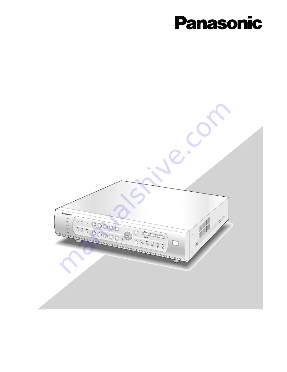
Digital Disk Recorder
Operating Instructions
Model No.
WJ-HD88
ERROR
ALARM
HDD
TIMER
1
2
3
4
5
6
7
8
9
0
MENU
ESC
ALARM
RESET
SEQUENCE
STILL
COPY 2
SET
PAUSE
REV
FWD
SKIP
STOP
PLAY
REC
Digital D
isk Recorder
WJ-HD
OPERATE
88
88