16
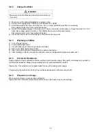
WARNING
WARNING
Positioning the unit
The water heater should be fitted level on a hard surface with sufficient load strength to take the full weight of cylinder.
Adjustable feet are fitted to ensure the unit can be adjusted to a level position. There is no limitations regarding the
fitting distance from walls etc., but it is strongly recommended to ensure easy access to all pipe fitting etc. There
should be at least 80 cm of free space in front of the water heater to ensure easy access for servicing and
maintenance.
Protection from frost
If the water heater is in danger of being exposed to frost while not operating under electric power, the unit must be
drained to avoid damage. Make sure the electric power is turned off before draining, otherwise the heating elements
can be damaged and the warranty is void.
Installation
1
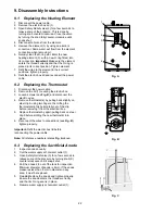
Install adjustable legs at bottom of tank (3 locations) then adjust the height until the unit stable.
2
Fix the anode bar into socket.
3
Install pressure reducing valve and safety valve at cold water supply, and connect water supply inlet through inlet
pipe.
4
Install drain valve appropriately.
5
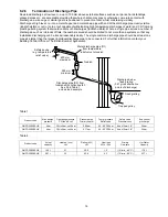
Install the Tundish in a vertical position within a maximum of 600 mm from the temperature and Pressure Relief
Valve drain connection. Ensure the expansion relief pipework discharge through the tundish. Tundish pipework
must be 22 mm with a minimum vertical length of 300 mm below tundish. Maximum permitted length of 22 mm
pipework is 9 m. Each bend or elbow is equivalent to 0.8 m of pipework.
Discharge pipe
Connect the discharge from the tundish. This must have a continuous fall and be fitted in accordance with The
Building Regulations. The tundish should be installed away from electrical devices.
6
Install Expansion vessel and connect to inlet pipe using Tee joint.
7
Install 3-way valve at outlet tube of indoor unit, connect heating tube connection with tank pipe.
Be careful on 3-way valve connecting direction
- “Default” condition is at Heating Side
- “On” condition is at Tank Unit
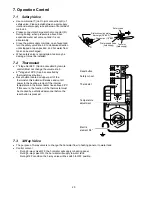
Insert sensor until it touches securely end of socket, tighten the cap of socket so that it is not shifted.
(Refer bottom diagram)
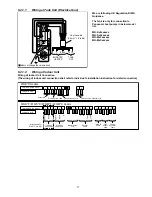
Connect the cable between heater and OLP, which located inside electrical box as shown at below section.
(Wiring at Tank Unit – (Electrical Box) and Wiring at Indoor Unit)
Use cap tire cable (2.5 mm
2
) for wiring.
For S*H series, 3 cables are needed.
While, for other models, 5 cables is needed.
Fix the cables to the cord protector mountings with cable ties to ensure strain relief closely.
Insert the cables of 3-way valve, sensor & heater from bushing at the bottom of indoor unit.
Guide the wire inside the indoor unit with refer to the installation instruction of indoor unit.
Please keep the space for maintenance purpose (Top: above 300 mm / Front: above 600 mm)


