background image

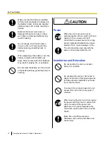
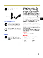
After installing or moving the unit, lock
the casters and set the fall-prevention
extension legs.

Locking the casters
(Push this side)

Push to lock

Operating Safeguards

If the unit falls down or gets damaged,
turn the unit off and unplug the power
cord. Otherwise, it may cause fire or
electric shock.

Do not lean against the screen or on the
cover (lower), even if the unit is mounted
on the wall.

Battery

When the unit is not used over an
extended period of time, take the
batteries out of the unit. Otherwise, the
batteries may leak. Do not use the leaked
batteries.

Safety Information (For
United Kingdom Only)

This appliance is supplied with a moulded three pin
mains plug for your safety and convenience.
A 5 amp fuse is fitted in this plug. Should the fuse need
to be replaced, please ensure that the replacement fuse
has a rating of 5 amps and that it is approved by ASTA
or BSI to BS1362. Check for the ASTA mark 

 or the

BSI mark   on the body of the fuse. If the plug contains
a removable fuse cover, you must ensure that it is
refitted when the fuse is replaced. If you lose the fuse
cover, the plug must not be used until a replacement
cover is obtained. A replacement fuse cover can be
purchased from your local Panasonic Dealer.

IF THE FITTED MOULDED PLUG IS UNSUITABLE
FOR THE SOCKET OUTLET IN YOUR PREMISES,
THEN THE FUSE SHOULD BE REMOVED AND THE
PLUG CUT OFF AND DISPOSED OF SAFELY.
THERE IS A DANGER OF SEVERE ELECTRICAL
SHOCK IF THE CUT OFF PLUG IS INSERTED INTO
ANY 13 AMP SOCKET.
If a new plug is to be fitted, please observe the wiring
code as shown below. If in any doubt, please consult a
qualified electrician.

WARNING

This appliance must be earthed.

IMPORTANT

The wires in this mains lead are coloured as
follows:

Green-and Yellow:

Earth

Blue:

Neutral

Brown:

Live

Operating Instructions (For Basic Operations)

11

1

For Your Safety

Содержание UB-T761

Страница 1: ...ges 37 through 60 Before operating this unit please read these instructions completely and keep them carefully for future reference This unit is designed for installation by a qualified servicing dealer Installation performed by non authorized individuals could cause safety related problems with the operation of this equipment For U S A only To locate the closest authorized dealer in your area ple...

Страница 2: ...th the elite Panaboard Also you can incorporate the external devices smoothly using the electronic pen Install Free Kit Optional Device By attaching this product to an elite Panaboard and turning the power on you can activate the elite Panaboard software It is not necessary to install the elite Panaboard software on your computer Usage Scenarios For Education Create an effective learning environme...

Страница 3: ...ating the elite Panaboard as well as instructions for installation construction For Software electronic documentation Instructions for the included elite Panaboard software and elite Panaboard book The manual Operating Instructions For Software is located on the included CD ROM You can view the Operating Instructions For Software after you install the elite Panaboard Software on your computer For ...

Страница 4: ... countries All other trademarks identified herein are the property of their respective owners Federal Communications Commission Requirements For United States Only Note This equipment has been tested and found to comply with the limits for a Class A digital device pursuant to part 15 of the FCC Rules These limits are designed to provide reasonable protection against harmful interference when the e...

Страница 5: ... greater Windows Vista Hard Disk Hard disk with at least 400 MB of free space not including the space required for saving files Note To run the elite Panaboard software Microsoft NET Framework 2 0 or later and DirectX 7 0 or later are required When you install the elite Panaboard software on the CD ROM NET Framework 2 0 will be installed on your computer if it is not already installed The system r...

Страница 6: ...nded use 3 Earthquake fire flood tidal wave hurricane lightning or other natural phenomena 4 Natural aging of the building or similar phenomena For FRG Users For Germany Only Note Machine noise information regulation 3 GPSGV the maximum sound pressure level is 70 dB A or less in conformity with EN ISO 7779 This equipment is not for use at video display work stations according to BildscharbV 6 Oper...

Страница 7: ... Pen 28 Replacing the Penpoint of the Electronic Pen 29 Troubleshooting 30 Specifications 32 Supplies Accessories 36 Installation Manual 37 Installation Manual for qualified service personnel 37 For Your Safety 37 Notice 37 Included Accessories 39 Wall Mounting Construction 41 Checking the Wall 41 Installing the Wall Mounting Plates 42 Wall Types and Installation Procedures 45 Stand Assembly Sold ...

Страница 8: ...ith the proper voltage If you use a cord with an unspecified current rating the unit or plug may emit smoke or become hot to the touch When you operate this product the power outlet should be near the product and easily accessible To ensure safe operation the power cord supplied must be inserted into a standard three prong AC outlet which is effectively grounded earthed through the normal wiring T...

Страница 9: ...cord forcibly can damage it and cause fire or electric shock During thunderstorms do not touch the unit and plug It may cause an electric shock Installation and Relocation Have the unit installed removed and disposed of only by qualified service personnel When the unit will no longer be used in order to prevent it from falling do not leave the unit installed but remove it If the unit falls it can ...

Страница 10: ...d period of time switch it off and unplug it If an unused unit is left connected to a power source for a long period degraded insulation may cause electric shock current leakage or fire The unit should be used only with the power cord enclosed with the unit Installation and Relocation Do not position the unit in a location where it is unstable Do not place the unit in a hot humid or dusty environm...

Страница 11: ...s a rating of 5 amps and that it is approved by ASTA or BSI to BS1362 Check for the ASTA mark or the BSI mark on the body of the fuse If the plug contains a removable fuse cover you must ensure that it is refitted when the fuse is replaced If you lose the fuse cover the plug must not be used until a replacement cover is obtained A replacement fuse cover can be purchased from your local Panasonic D...

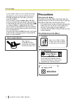
Страница 12: ...partment with a screwdriver and replace the fuse and fuse cover Precautions About Using the Battery If a battery is used improperly the battery may leak causing corrosion of the unit or it may burst To prevent this always follow the precaution given below If the electronic pen ceases to function because the battery has run out remove it immediately and dispose of it according to local regulations ...

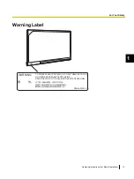
Страница 13: ...䚼 㞾Ꮕৃҹ㓈ׂⱘ䚼ߚDŽ 㓈ׂџᅰࡵ䇋ྨᠬ 䌘Ḑⱘ㓈ׂҎਬDŽ PBQAA0582ZA WARNING TO PREVENT ELECTRIC SHOCK DO NOT REMOVE COVER NO USER SERVICEABLE PARTS INSIDE REFER SERVICING TO QUALIFIED SERVICE PERSONNEL Operating Instructions For Basic Operations 13 1 For Your Safety ...
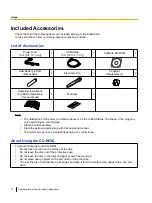
Страница 14: ... the United States The shape of the plug may vary depending on country area Stand is sold separately Store the extra penpoint along with this operating manual The warranty may not be included depending on country area About Using the CD ROM To prevent damage to the CD ROM Do not touch or write on the surface of the disc Do not leave the disc out of the protective case Do not leave the disc in the ...

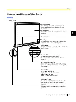
Страница 15: ...o input port in stereo Volume Dial Adjusts the volume of the speaker The volume indicator is set in the center when shipped External Audio Input Port Connect the audio output port of a VCR or DVD player etc to this port and hear sound through the USB speaker Status LEDs Left Power LED green Lights green when the power is on Right Error LED red Blinks red when an error occurs USB Hub 2 Ports You ca...

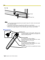
Страница 16: ...ealer Electronic Pen Penpoint When you push down on the penpoint ultrasonic waves and infrared signals are transmitted and equivalent of a left mouse click is performed Ultrasonic Emitter Do not block this area with your fingers Doing so will prevent the elite Panaboard from correctly detecting the electronic pen s position Infrared Emitter Do not block this area with your fingers Doing so will pr...

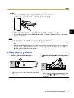
Страница 17: ...he pen from power save mode by pushing the penpoint the pen s reaction may be slow When operating the electronic pen you will hear a buzzing sound due to the pen emitting ultrasonic waves for location detection This sound does not have any negative effects for nearby people or devices It will not cause electrical shocks Inserting Replacing Batteries 1 Remove replace the battery cover When replacin...

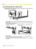
Страница 18: ...ional stand plug the power cord into the AC inlet and secure the cord as shown in the illustrations below When attaching the power cord downward When attaching the power cord along the lower side of the elite Panaboard About Grounding If you cannot connect the grounding line contact your dealer The cost of installing a grounding connection is not included in the price of the elite Panaboard The in...

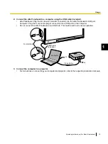
Страница 19: ...ger connector into a USB port on the computer Do not connect the elite Panaboard via a USB hub This could result in erroneous operation AC AC USB Cable Included Computer Projector Video Cable To USB Port 3 Connect the computer to a projector For instructions on connecting your computer and projector refer to the respecting instruction manuals Operating Instructions For Basic Operations 19 1 Usage ...

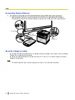
Страница 20: ...SB Cable Sold Separately To USB Port Flatbed Scanner MFP To USB Port About the Usage Location Do not place the elite Panaboard where it is directly exposed to sunlight near a stove near to a heating cooling vent or exposed to strong winds Do not use the elite Panaboard in a location less than 10 C 50 F or in a location subject to extreme changes in temperature Note The elite Panaboard may not work...

Страница 21: ...e elite Panaboard off wait more than 2 seconds before turning it back on Moving the elite Panaboard When Using the Stand Sold Separately 1 Make sure that the power switch is set to O OFF and disconnect the power cord and USB cable 2 Release the locks on the casters 3 Move the elite Panaboard avoid banging or shaking the board Notice Always move the elite Panaboard with 2 people Do not drag or step...

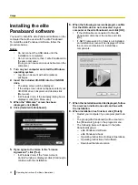
Страница 22: ...terms in the License Agreement click Yes In Windows Vista if the User Account Control window is displayed click Continue to continue with the installation 6 When the following screen is displayed confirm that the USB cable is not connected to your computer or the elite Panaboard and click OK If the USB cable is connected to the elite Panaboard disconnect the cable and click OK If NET Framework 2 0...

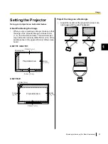
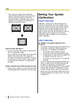
Страница 23: ...y not function correctly within 50 mm 2 in of the position sensor in the upper left corner of the screen board UB T781 UB T761 Projectable Area 5 mm 1 4 in 5 mm 1 4 in 50 mm 2 in 5 mm 1 4 in UB T781W Projectable Area 50 mm 2 in 5 mm 1 4 in 5 mm 1 4 in 5 mm 1 4 in Project the Image as a Rectangle Adjust the location of the projector to project at a right angle with the elite Panaboard Operating Ins...

Страница 24: ...l be correctly displayed on the image projected onto the screen board Be sure to perform calibration before use After you have set up the elite Panaboard project an image onto the screen board and use the elite Panaboard software installed on your computer to perform calibration After Calibration Do Not Move the elite Panaboard or the Projector The position of projected image and electronic pen wi...

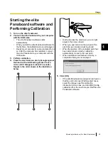
Страница 25: ...s of each circle until it disappears about 2 seconds Repeat in the order shown in the illustration below A B C D E Hold and press the electronic pen at a right angle to the screen board When you push down on the penpoint the electronic pen makes a buzzing sound When the position of the indicated point has been determined correctly calibration automatically moves to the next point When calibration ...

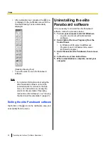
Страница 26: ...Exiting the elite Panaboard software Right click on the icon in the notification area and select Exit from the menu Uninstalling the elite Panaboard software If it is necessary to uninstall the elite Panaboard software follow the procedure below 1 Turn on your computer and start Windows Log into an account with Administrator privileges 2 Select Add or Remove Programs from the Control Panel In Wind...

Страница 27: ...ws 2000 Programs is displayed instead of All Programs Note To view the electronic documentation you must have Adobe Reader installed on your computer If your computer is connected to the Internet you can download Adobe Reader from Adobe s web site Download the Latest Software Follow the procedure below to download the latest version of the software from the download web site 1 Turn on your compute...

Страница 28: ...e battery in the electronic pen is low the message The pen battery is low Replace the battery soon will be displayed on the computer screen Continued use of the electronic pen can lead to poor performance Replace the battery as soon as possible See Inserting Replacing Batteries page 17 for details on replacing the battery Dispose of expired batteries quickly by covering the terminals in tape and f...

Страница 29: ...en becomes worn a hole will appear in the penpoint Continuing to use the electronic pen in this condition can cause damage to the screen or unsatisfactory operation so replace the penpoint with a new one as soon as possible Operating Instructions For Basic Operations 29 1 Appendix ...

Страница 30: ...n 25 Drawn lines and comments are not completely displayed or are displayed in the wrong location The electronic pen loses the functions You are holding the electronic pen at an angle You are operating the elite Panaboard in direct sunlight or other strong lighting Infrared controllers e g a television remote control are being used and pointed towards the position sensor There is a wall or ceiling...

Страница 31: ...e of your computer is low or set to mute Adjust the volume using the volume control in the notification area or uncheck the mute setting The volume of the application is low Adjust the volume of the application e g Windows Media Player The connection between the external audio input port and the VCR or DVD player etc is not correct Securely connect the external audio input port and the VCR or DVD ...

Страница 32: ...Humidity 15 to 80 Interface USB 2 0 No of Hub Ports 2 ports Interactive Features Electronic Pen Power LR03 AAA alkaline dry cell battery 1 Electronic Pen Battery Life 30 hours when used continuously at 25 C 77 F When using Panasonic LR03 alkaline dry cell batteries Audio Features Audio Input Input level 309 mVrms 1 KHz 0 dB 10 kW Stereo 1 system ø 3 5 mm 1 8 in stereo mini jack Audio Output 2 W 2 ...

Страница 33: ... in Interactive Features Effective Area Height Width 1 165 mm 1 502 mm 3 ft 9 7 8 in 4 ft 11 1 8 in Project the image so that it is at least 5 mm 1 4 in from the screen frame The electronic pen may not function correctly within 50 mm 2 in of the position sensor in the upper left corner of the screen board Projectable Area 5 mm 1 4 in 5 mm 1 4 in 50 mm 2 in 5 mm 1 4 in 77 in Operating Instructions ...

Страница 34: ... 6 ft 3 8 in Interactive Features Effective Area Height Width 958 mm 1 829 mm 3 ft 1 3 4 in 6 ft Project the image so that it is at least 5 mm 1 4 in from the screen frame The electronic pen may not function correctly within 50 mm 2 in of the position sensor in the upper left corner of the screen board Projectable Area 5 mm 1 4 in 5 mm 1 4 in 50 mm 2 in 83 in 5 mm 1 4 in 34 Operating Instructions ...

Страница 35: ...4 in Interactive Features Effective Area Height Width 967 mm 1 239 mm 3 ft 2 1 8 in 4 ft 3 4 in Project the image so that it is at least 5 mm 1 4 in from the screen frame The electronic pen may not function correctly within 50 mm 2 in of the position sensor in the upper left corner of the screen board Projectable Area 5 mm 1 4 in 5 mm 1 4 in 50 mm 2 in 5 mm 1 4 in 64 in Operating Instructions For ...

Страница 36: ... Electronic Pen UE 608025 Stand KX B061 1 Stand UE 608030 Install Free Kit UE 608050 1 KX B061 is not available for the UB T761 To purchase separately sold items contact your dealer 36 Operating Instructions For Basic Operations Appendix ...

Страница 37: ...NG Denotes a potential hazard that could result in serious injury or death CAUTION Denotes hazards that could result in minor injury or damage to the unit These symbols are used to alert operators to a specific operating procedure that must not be performed These symbols are used to alert operators to a specific operating procedure that must be emphasized in order to operate the unit safely Notice...

Страница 38: ...t least the following weight 1 373 N 140 kgf Do not attach the electronic board to mortared walls Accidental electric leakage from the wall mounting plate bolts to metal laths or wire laths can cause heat smoke or a fire Confirm the bolts of the unit are certainly caught by the wall mounting plate by pulling the unit after hanging the unit on the wall mounting plate if the unit is mounted on a wal...

Страница 39: ...omputer connection CD ROM 1 Operating Instructions For Software Drivers Application software Cable Holder 1 For power cord Wall Mounting Plate Left 1 Wall Mounting Plate Right 1 Battery LR03 AAA alkaline battery 1 For electronic pen Electronic Pen 1 Penpoint Replacement 2 For electronic pen Cable Tie 1 Fastener for power cord when mounted on a wall Operating Instructions 1 Operating Instructions F...

Страница 40: ...May not be included depending on country area Notice Screws 8 count for wall mounting are not included Please purchase screws with a size of M6 appropriate for your type of wall page 45 40 Operating Instructions For Basic Operations Installation Manual ...

Страница 41: ...r fire I Necessary Tools and Parts not included with the elite Panaboard Drill Screwdriver Measuring tape Level 8 screws M6 size II Before Starting 1 Make sure that the wall is strong enough to support the elite Panaboard Rated strength greater than 1 373 N 140 kgf Notice If necessary reinforce the wall so that it is strong enough to support the elite Panaboard 2 Make sure that the location is lar...

Страница 42: ...to insert the screws UB T781 813 mm 2 ft 8 in 40 mm 1 9 16 in 982 mm 3 ft 2 21 32 in 30 mm 1 3 16 in 44 mm 1 23 32 in 222 5 mm 8 3 4 in 469 5 mm 1 ft 6 15 32 in 725 mm 2 ft 4 17 32 in UB T781W 813 mm 2 ft 8 in 40 mm 1 9 16 in 982 mm 3 ft 2 21 32 in 30 mm 1 3 16 in 44 mm 1 23 32 in 222 5 mm 8 3 4 in 543 mm 1 ft 9 3 8 in 725 mm 2 ft 4 17 32 in 42 Operating Instructions For Basic Operations Installat...

Страница 43: ... plate The remaining 4 screws are used after installing the elite Panaboard on the wall 40 mm 1 9 16 in 30 mm 1 3 16 in 44 mm 1 23 32 in UB T781 UB T781W 813 mm 2 ft 8 in UB T761 550 mm 1 ft 9 21 32 in UB T781 UB T781W 982 mm 3 ft 2 21 32 in UB T761 784 mm 2 ft 6 7 8 in Screws 8 count are not included with the elite Panaboard Please purchase screws with a size of M6 appropriate for your type of wa...

Страница 44: ...5 Mount the elite Panaboard on the wall See Assembling the elite Panaboard For Wall Mounting page 52 44 Operating Instructions For Basic Operations Installation Manual ...

Страница 45: ... walls Stud plugs not included are needed Drill bit Metal or concrete wall Stud plug Wall mounting plate Bolt Insert a stud plug in the hole Drill eight holes in the wall For the correct hole size refer to the instructions for the particular stud plugs used Insert the bolt through the hole in the wall mounting plate and tighten until the wall mounting plate is securely fixed to the wall Operating ...

Страница 46: ...the arms expand pull the wall mounting plate out until the arms of the split wing toggle grip firmly into the wall Tighten the bolt until the wall mounting plate is securely fixed into the wall Wooden walls Wood screws not included are needed Wall mounting plate Wood screw Wooden wall Insert the wood screw through the hole in the wall mounting plate and tighten until the wall mounting plate is sec...

Страница 47: ... M6 45 mm 1 3 4 in 10 Two wing Bolt M5 12 mm 1 2 in 1 2 Support Bracket 2 Fall prevention Extension Leg 4 Screw M6 60 mm 2 3 8 in 4 Nut 4 Wrench 2 1 Washer 10 1 Use the two wing bolts F when securing the elite Panaboard to the stand 2 The included wrench is necessary for tightening and loosening the screw E so keep it in a safe location Operating Instructions For Basic Operations 47 1 Installation...

Страница 48: ...fore assembly be sure to lock the casters Locking the casters Push this side Assembly Instructions 1 Assemble the fall prevention extension legs 48 Operating Instructions For Basic Operations Installation Manual ...

Страница 49: ...e front Locking caster side rear Locking caster side rear Notice Do not over tighten the screw Doing so can warp the support beams Assemble the stand so that the locking casters are on the rear side Operating Instructions For Basic Operations 49 1 Installation Manual ...

Страница 50: ...folding back the fall prevention extension legs release the lock as follows 1 2 1 1 2 4 Mount the elite Panaboard See Assembling the elite Panaboard For Mounting on a Stand Sold Separately page 55 50 Operating Instructions For Basic Operations Installation Manual ...

Страница 51: ... Wall Mounting Plate Right Left 1 Each Battery 1 Electronic Pen 1 Penpoint 2 Cable Tie 1 Operating Instructions 1 Warranty 1 Notice When handling the screen board hold it by the edge frame and not the screen board itself Holding the screen board can result in damage The packing materials in the shipping box are necessary for repackaging so keep them in a safe place Note The warranty may not be inc...

Страница 52: ...e tie fastening hole behind the control power cover back 3 Pull the loose end of the cable tie to tighten it and install the power cord depending on the location of the outlet as illustrated in the following diagrams When attaching the power cord downward Fasten the power cord with the cable tie When attaching the power cord along the lower side of the elite Panaboard Fasten the power cord with th...

Страница 53: ...after sliding the attachment cover down as shown in the right sided illustration above 5 Hang the elite Panaboard on the wall mounting plates with the screw heads 6 Unscrew the 4 screws from the front lower frame cover 7 Lift the bottom of the front lower frame cover to remove it Note The main unit and the USB speakers on the front lower frame cover are connected with the cable Be careful not to d...

Страница 54: ...wer frame cover to the elite Panaboard and fix it using 4 screws ensuring that the cover is flush with the main unit Notice When mounting on a wall do not hit or jolt the elite Panaboard After mounting gently apply some weight on the elite Panaboard to make sure that it is securely fastened to the wall Note After installation is complete use the included cable holder to manage the power cord and U...

Страница 55: ... Panaboard can operate See Confirming the elite Panaboard Operation page 57 For Mounting on a Stand Sold Separately 1 Attach the power cord Connect the power cord to the elite Panaboard before installing on the stand Power Cord 2 Depending on the location of the outlet install the power cord as illustrated in the following diagrams When attaching the power cord downward When attaching the power co...

Страница 56: ...d securely insert them at the desired height Torque greater than 1 N m 10 kgf cm 9 lbf in elite Panaboard Height Screw Position 100 mm 3 7 8 in Highest Standard 2nd from top 100 mm 3 7 8 in 2nd from bottom 200 mm 7 7 8 in Lowest 5 Wipe the screen board surface Gently wipe the screen board surface with a soft moist cloth Notice Do not use thinner benzene or abrasive chemicals to clean Doing so can ...

Страница 57: ...ating correctly If a projector is not available confirm operation using only the elite Panaboard and computer When the elite Panaboard software starts the calibration screen is displayed on the computer screen Perform tentative calibration by pressing the 5 points on the elite Panaboard with the electronic pen as shown in the illustration below For precise adjustment it is necessary to use a proje...

Страница 58: ...parately page 55 in reverse Package the unit as depicted in the diagram in Preparing for Removing the elite Panaboard from Its Packaging page 51 Notice When handling the screen board hold it by the frame and not the screen board itself Holding the screen board can result in the damage 58 Operating Instructions For Basic Operations Installation Manual ...

Страница 59: ...ont lower frame cover to remove it Note The main unit and the USB speakers on the front lower frame cover are connected with the cable Be careful not to damage the connectors 3 Disconnect the 2 connectors from the audio board A 1 4 Unscrew the 4 screws and remove the control power cover front Operating Instructions For Basic Operations 59 1 Installation Manual ...

Страница 60: ... main unit using the 7 screws and fix the black cable and white cable to their previous positions using the clamper 9 Attach the control power cover front to the main unit using the 4 screws 10 Attach the connectors from the USB speakers to the audio board and attach the front lower frame cover to the main unit 11 Fix the front lower frame cover using the 4 screws 60 Operating Instructions For Bas...

Страница 61: ...Operating Instructions For Basic Operations 61 1 Notes ...

Страница 62: ...62 Operating Instructions For Basic Operations Notes ...

Страница 63: ...Operating Instructions For Basic Operations 63 1 Notes ...

Страница 64: ... For business users in the European Union If you wish to discard electrical and electronic equipment please contact your dealer or supplier for further information Information on Disposal in other Countries outside the European Union These symbols are only valid in the European Union If you wish to discard these items please contact your local authorities or dealer and ask for the correct method o...

Отзывы:

Похожие инструкции для UB-T761