3. Use only a grounded-tip soldering iron to solder or unsolder ES
devices.
4. Use only an anti-static solder removal device. Some solder
removal devices not classified as "anti-static (ESD protected)" can
generate electrical charge sufficient to damage ES devices.
5. Do not use freon-propelled chemicals. These can generate
electrical charges sufficient to damage ES devices.
6. Do not remove a replacement ES device from its protective
package until immediately before you are ready to install it. (Most
replacement ES devices are packaged with leads electrically
shorted together by conductive foam, alminum foil or comparable
conductive material).
7. Immediately before removing the protective material from the
leads of a replacement ES device, touch the protective material to
the chassis or circuit assembly into which the device will be
installed.
Caution
Be sure no power is applied to the chassis or circuit, and observe
all other safety precautions.
8. Minimize bodily motions when handling unpackaged replacement
ES devices. (Otherwise hamless motion such as the brushing
together of your clothes fabric or the lifting of your foot from a
carpeted floor can generate static electricity (ESD) sufficient to
damage an ES device).
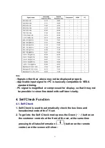
3. Applicable signals
Applicable input signal for Component (Y, P
B
, P
R
), HDMI and PC (D-sub 15P) (* Mark)
5
Содержание TX-26LX500F
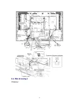
Страница 12: ...6 4 Wire dressing 2 Clamping 12 ...
Страница 24: ...24 ...
Страница 25: ...8 3 Option Description 25 ...
Страница 26: ...26 ...
Страница 32: ...13 2 Front Chassis Layout 13 3 Cabinet Ass y Layout 32 ...
Страница 33: ...13 4 Packing 33 ...
Страница 58: ...IC2108 C0EBF0000354 IC 1 58 ...
Страница 63: ...L8501 ELJNA2R7JB INDUCTION COIL 1 63 ...
Страница 105: ...IC1104 C2CBYF000032 IC 1 105 ...
Страница 107: ...IC5015 C0CBCAD00016 IC 1 107 ...
Страница 111: ...Q1119 2SA207700L TRANSISTOR 1 111 ...
Страница 162: ...11 Schematic Diagram 11 1 Schematic Diagram Notes 35 ...
Страница 163: ...11 Schematic Diagram 11 1 Schematic Diagram Notes 35 ...


