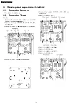
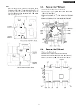

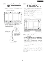


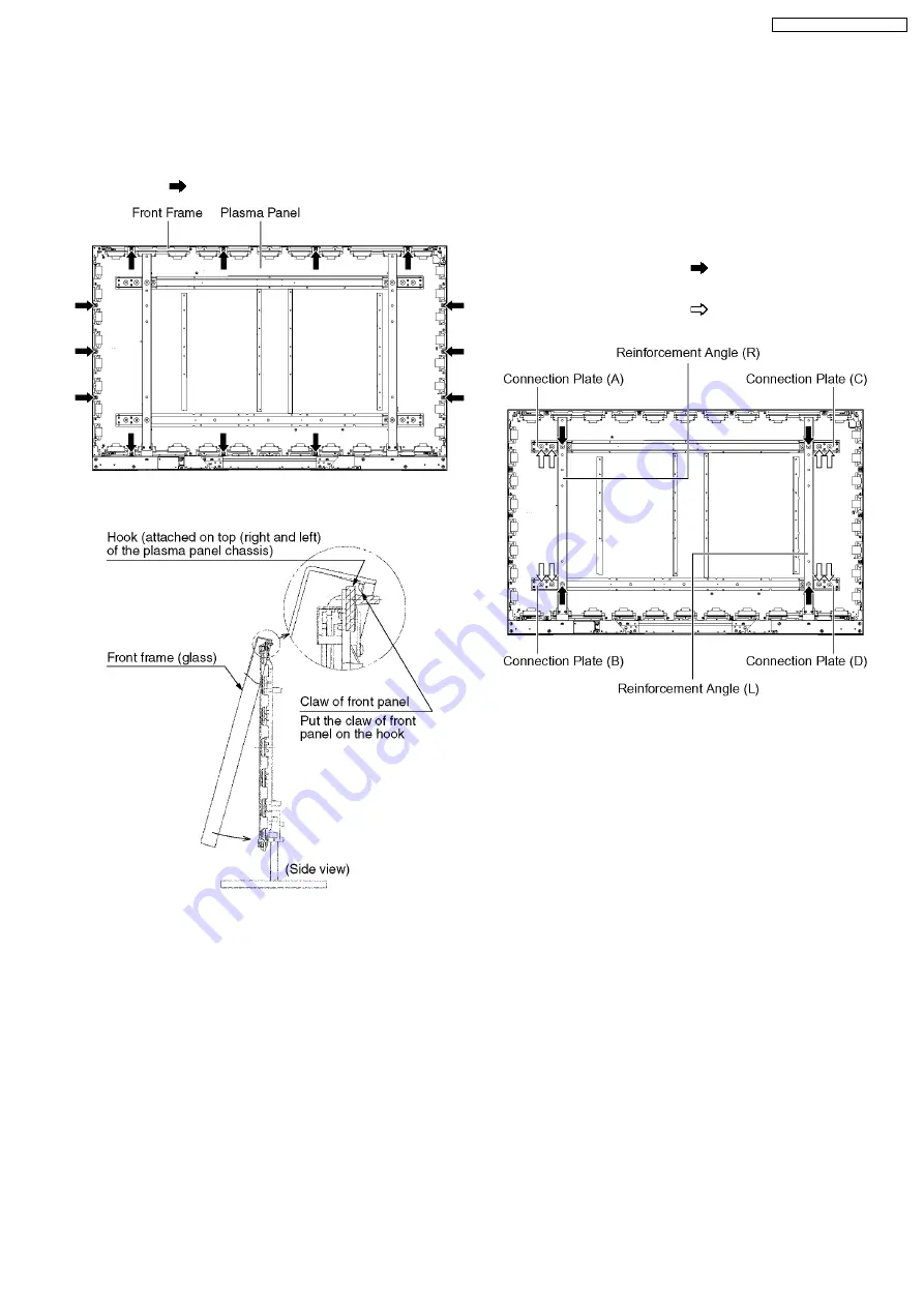
6.34. Remove the Plasma panel
section from the Front frame
(glass)
1. Remove the front frame and the plasma panel fastening
screw (×13
).
2. For leaving the plasma panel from the front frame, pull the
bottom of the front frame forward, lift, and remove.
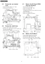
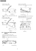
6.35. Remove the Reinforcement
Angles (L, R) and the
Connection Plate (A, B, C, D)
1. Remove the plasma panel section from the servicing stand
and lay on a flat surface such as a table (covered), with the
plasma panel surface facing downward.
Spread a soft cloth or similar on the table for protection, so
the panel surface is not scratched.
2. Remove the screws (×2
each) and remove the
Reinforcement Angles (L, R).
3. Remove the screws (×2
each) and remove the
Connection Plate (A, B, C, D).
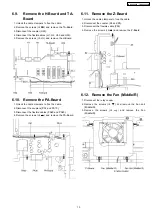
6.36. Replace the plasma panel
(finished)
1. Place the new plasma panel (finished) on the flat surface of
the table (covered by a soft cloth), with the plasma panel
surface facing downward.
2. Attach the C1, C2, C3,C4,C5-Board and the C6-Board,
connect the flexible cables (×22) from the Plasma panel to
the C1, C2, C3,C4,C5-Board and the C6-Board, and fit the
flexible cable holders.
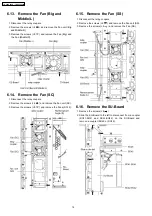
3. Attach the Hooks (left, right) and fit the Reinforcement
Angles (L, R) and the Connection Plate (A, B, C, D) to the
new plasma panel.
4. Place the plasma panel section on the servicing stand.
5. Attach the front frame and each P.C.Board and so on, to
the new plasma panel.
* When fitting the front frame, be careful to allow any debris,
dust or handling residue to remain between the front glass and
plasma panel.
21
TH-65PV500E / TH-65PV500B
Содержание TH-65PV500E
Страница 5: ...1 Applicable signals 5 TH 65PV500E TH 65PV500B ...
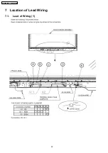
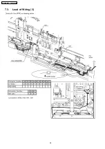
Страница 22: ...7 Location of Lead Wiring 7 1 Lead of Wiring 1 22 TH 65PV500E TH 65PV500B ...
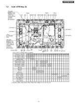
Страница 23: ...7 2 Lead of Wiring 2 23 TH 65PV500E TH 65PV500B ...
Страница 24: ...7 3 Lead of Wiring 3 24 TH 65PV500E TH 65PV500B ...
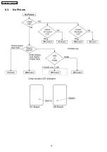
Страница 28: ...8 3 No Picture 28 TH 65PV500E TH 65PV500B ...
Страница 31: ...31 TH 65PV500E TH 65PV500B ...
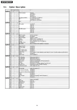
Страница 32: ...9 3 Option Description 32 TH 65PV500E TH 65PV500B ...
Страница 33: ...33 TH 65PV500E TH 65PV500B ...
Страница 42: ...42 TH 65PV500E TH 65PV500B ...
Страница 78: ...TH 65PV500E TH 65PV500B 78 ...
Страница 79: ...14 Block and Schematic Diagram 14 1 Schematic Diagram Notes TH 65PV500E TH 65PV500B 79 ...
Страница 153: ...15 Parts Location Mechanical Replacement Parts List 15 1 Parts Location 153 TH 65PV500E TH 65PV500B ...
Страница 154: ...15 2 Packing Exploded Views 1 154 TH 65PV500E TH 65PV500B ...
Страница 155: ...15 3 Packing Exploded Views 2 155 TH 65PV500E TH 65PV500B ...
Страница 156: ...15 4 Packing Exploded Views 3 156 TH 65PV500E TH 65PV500B ...
Страница 159: ...16 Electrical Replacement Parts List 16 1 Replacement Parts List Notes 159 TH 65PV500E TH 65PV500B ...