Wiring
© Panasonic Industrial Devices SUNX Co., Ltd. 2020
64
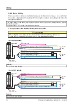
2-5-4 Basic Wiring
This is a common connection method whereby one emitter and one receiver face each other.
The control output (OSSD 1 / 2) turns OFF when light is blocked, and automatically turns ON
when light is received.
The output setting of the device is set by the connection of the output polarity setting / lockout release
input wire (pale blue).
If the wiring is not correct, the lockout state will activate.
●
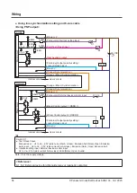
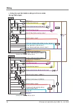
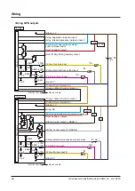
Using optical synchronization setting and 5-core cable
CAUTION
When using the 5-core cable, set the synchronization method to optical synchronization.
For the setting of optical synchronization, refer to
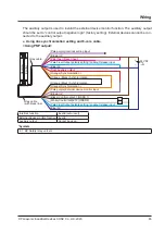
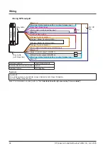
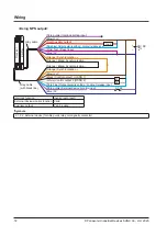
<Using PNP output>
Emitter
Receiver
K1
K2
+ 24V DC
+20
-30
%
−
+ 24V DC
+20
-30
%
−
Gray cable
Gray cable
(with black line)
(Brown) +V
(Brown) +V
(Pink) Test input
(Pale blue) Output polarity setting / Lockout release input
(Pale blue) Output polarity setting / Lockout release input
(Blue) 0V
(Blue) 0V
(Black) Control output 1 (OSSD 1)
(White) Control output 2 (OSSD 2)
*Symbols
K1, K2: Safety relay unit, etc.
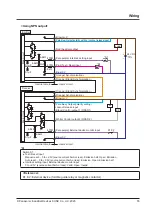
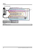
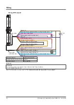
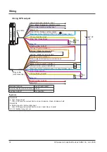
<Using NPN output>
Emitter
Receiver
K1
K2
+ 24V DC
+20
-30
%
−
+ 24V DC
+20
-30
%
−
Gray cable
Gray cable
(with black line)
(Brown) +V
(Brown) +V
(Pink) Test input
(Pale blue) Output polarity setting / Lockout release input
(Pale blue) Output polarity setting / Lockout release input
(Blue) 0V
(Blue) 0V
(Black) Control output 1 (OSSD 1)
(White) Control output 2 (OSSD 2)
*Symbols
K1, K2: Safety relay unit, etc.
Содержание SF4D-*-01 Series
Страница 2: ... Panasonic Industrial Devices SUNX Co Ltd 2020 2 MEMO ...
Страница 6: ... Panasonic Industrial Devices SUNX Co Ltd 2020 6 MEMO ...
Страница 120: ...Functions Panasonic Industrial Devices SUNX Co Ltd 2020 120 MEMO ...
Страница 134: ...Troubleshooting Panasonic Industrial Devices SUNX Co Ltd 2020 134 MEMO ...
Страница 168: ... Panasonic Industrial Devices SUNX Co Ltd 2020 168 MEMO ...


