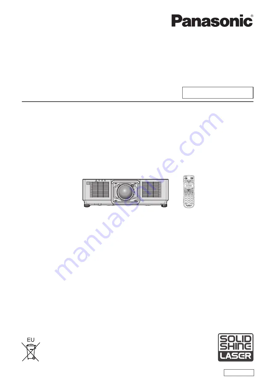
Panasonic PT-MZ10K Скачать руководство пользователя страница 1

Thank you for purchasing this Panasonic product.


The Operating Instructions correspond to the firmware’s main version 1.19 and higher.


This manual is common to all the models regardless of suffixes of the Model No.


z

for USA, Canada, EU countries, Korea, Taiwan

LB: Black model   

LW: White model


z

for India

LBD: Black model


z

for other countries or regions with power cord for 100 V - 120 V

LBX: Black model


LWX: White model


z

for other countries or regions with power cord for 200 V - 240 V

LBE: Black model 

LWE: White model


Before operating this product, please read the instructions carefully and save this manual 

for future use.


Before using this product, be sure to read “Read this first!” (

x

 pages 5 to 16).

DPQP1299ZE/X1

LCD Projector  

Commercial Use

Operating Instructions

Functional Manual

ENGLISH

Model No. 

PT-MZ16K


PT-MZ13K


PT-MZ10K

The projection lens is sold separately.

Содержание PT-MZ10K

Страница 1: ...r countries or regions with power cord for 100 V 120 V LBX Black model LWX White model z z for other countries or regions with power cord for 200 V 240 V LBE Black model LWE White model Before operating this product please read the instructions carefully and save this manual for future use Before using this product be sure to read Read this first x pages 5 to 16 DPQP1299ZE X1 LCD Projector Commerc...

Страница 2: ...using DIGITAL LINK 49 Connecting example when using the contrast synchronization function shutter synchronization function 50 Chapter 3 Basic Operations Switching on off the projector 53 Connecting the power cord 53 Power indicator 55 Switching on the projector 56 When the initial setting screen is displayed 57 Making adjustments and selections 64 Switching off the projector 65 Projecting 66 Selec...

Страница 3: ...UT 131 STANDBY MODE 131 QUICK STARTUP 132 NO SIGNAL SETTING 132 INITIAL STARTUP 135 STARTUP INPUT SELECT 135 DATE AND TIME 136 SCHEDULE 137 MULTI PROJECTOR SYNC 138 RS 232C 140 REMOTE1 MODE 142 FUNCTION BUTTON 142 FILTER COUNTER 143 STATUS 143 INFO MONITOR SETTING 145 DATA CLONING 147 SAVE ALL USER DATA 147 LOAD ALL USER DATA 147 INITIALIZE 147 SERVICE PASSWORD 149 TEST PATTERN menu 150 TEST PATTE...

Страница 4: ... the firmware 200 Updating the firmware via LAN 200 Chapter 6 Maintenance Light source temperature filter indicators 207 When an indicator lights up 207 Maintenance replacement 209 Before performing maintenance replacement 209 Maintenance 209 Replacing the unit 212 Troubleshooting 213 SELF TEST indications 215 Chapter 7 Appendix Technical information 218 PJLink protocol 218 Using Art Net function ...

Страница 5: ...n earthing type mains socket This is a safety feature If you are unable to insert the plug into the mains socket contact an electrician Do not defeat the purpose of the earthing plug WARNING This equipment is compliant with Class A of CISPR32 In a residential environment this equipment may cause radio interference for Taiwan WARNING This equipment complies with the Class A standard of CNS13438 Thi...

Страница 6: ...n point within an equilateral triangle is intended to alert the user to the presence of important operating and maintenance servicing instructions in the literature accompanying the product WARNING Do not look at the light emitted from the lens while the projector is being used As with any bright source do not stare into the direct beam RG2 IEC 62471 5 2015 Indicated on the projector Notice on las...

Страница 7: ...controls or adjustments or performance of procedures other than those specified herein may result in hazardous radiation exposure CAUTION North Middle South America Power Supply This Projector is designed to operate on 100 V 240 V 50 Hz 60 Hz AC house current only CAUTION The AC power cord which is supplied with the projector as an accessory can only be used for power supplies up to 125 V If you n...

Страница 8: ...KLBE PT MZ10KLWE PT MZ10KLBX PT MZ10KLWX Trade Name Panasonic Responsible Party Panasonic Corporation of North America Address Two Riverfront Plaza Newark NJ 07102 5490 General Contact http www panasonic com support Projector Contact https panasonic net cns projector This device complies with Part 15 of the FCC Rules Operation is subject to the following two conditions 1 This device may not cause ...

Страница 9: ... 13 amp socket If a new plug is to be fitted please observe the wiring code as shown below If in any doubt please consult a qualified electrician WARNING THIS APPLIANCE MUST BE EARTHED IMPORTANT The wires in this mains lead are colored in accordance with the following code Green and Yellow Earth Blue Neutral Brown Live As the colors of the wire in the mains lead of this appliance may not correspon...

Страница 10: ...zard distance within RG3 range In case of risk group 2 it can be used safely without damaging the eyes in any condition The combination of the projector and the projection lens which the hazard distance exceeds 1 m 39 3 8 and is categorized as risk group 3 is as follows Model No Projection lens Model No Use condition Risk group PT MZ16K ET EMT700 1 When the throw ratio is 2 9 1 or less Risk group ...

Страница 11: ...УППУ РИСКА RG3 ТОЛЬКО ДЛЯ ПРОФЕССИОНАЛЬНОГО ИСПОЛЬЗОВАНИЯ И ОН НЕ ПРЕДНАЗНАЧЕН ДЛЯ ИСПОЛЬЗОВАНИЯ ПОТРЕБИТЕЛЯМИ ПРИ ИСПОЛЬЗОВАНИИ СМЕННЫХ ПРОЕКЦИОННЫХ ОБЪЕКТИВОВ ПРИ УСЛОВИИ ЧТО ПРОЕКЦИОННОЕ ОТНОШЕНИЕ THROW RATIO БОЛЬШЕ ЧЕМ 3 4 ПЕРЕД НАЧАЛОМ РАБОТЫ ОБРАТИТЕСЬ К ИНСТРУКЦИЯМ ПО ЭКСПЛУАТАЦИИ ЧТОБЫ УЗНАТЬ ПРО ОПАСНОЕ РАССТОЯНИЕ 이 프로젝터는 투사 비율이 3 4보다 큰 교체식 투사 렌즈를 사용한 경우 전문가 전용인 RG3 등급이 될 수 있으며 일반 소비자용이 아...

Страница 12: ...ctric shocks Use an outlet supporting 15 A independently Using an outlet together with another device may result in fires due to heat generation Do not overload the wall outlet If the power supply is overloaded ex by using too many adapters overheating may occur and fire will result Clean the power plug regularly to prevent it from becoming covered in dust Failure to observe this will cause a fire...

Страница 13: ...he ceiling should only be carried out by a qualified technician If installation is not carried out and secured correctly it can cause injury or accidents such as electric shocks r r ACCESSORIES Do not use or handle the batteries improperly and refer to the following Failure to observe this will cause burns batteries to leak overheat explode or catch fire f f Do not use unspecified batteries f f Do...

Страница 14: ...ot place the projector in extremely hot locations Doing so will cause the outer casing or internal components to deteriorate or result in fire f f Take particular care in locations exposed to direct sunlight or near heaters Do not place your hands in the openings beside the optical lens while shifting the lens Failure to observe this could cause injury Do not install the projector in a location wh...

Страница 15: ... Do not attach the air filter unit while it is wet Doing so may result in electric shock or malfunctions f f After you clean the air filter units dry them thoroughly before reattaching them Ask your dealer about cleaning inside the projector every 20 000 hours of usage as an estimated duration Continuous use while dust is accumulated inside the projector may result in fire f f For cleaning fee ask...

Страница 16: ...o pela bateria pode irritar a garganta danificar o lacre do invólucro ou o vazamento provocar calor ruptura da blindagem e produzir fogo devido ao curto circuito dos terminais Não incinere nem aqueça as baterias elas não podem ficar expostas a temperaturas superiores a 100 C 212 F O gás liberado pela bateria pode irritar a garganta danificar o lacre do invólucro ou o vazamento provocar calor ruptu...

Страница 17: ...rporates the following software 1 the software developed independently by or for Panasonic Corporation 2 the software owned by third party and licensed to Panasonic Corporation 3 the software licensed under the GNU General Public License Version 2 0 GPL V2 0 4 the software licensed under the GNU LESSER General Public License Version 2 1 LGPL V2 1 and or 5 open source software other than the softwa...

Страница 18: ...wide range of usages is now possible With the superior compatibility with the devices other than projectors more advanced rendition in wide range of usage is possible Long life and high reliability The maintenance cost for long term operation is reduced by the unique light source cooling control technology and improvement of the dust resistance Also it will contribute to the stable operation by im...

Страница 19: ...ENGLISH 19 Chapter 1 Preparation This chapter describes things you need to know or check before using the projector ...

Страница 20: ...nditioner Depending on the conditions of use the screen may fluctuate in rare cases due to the heated air from the exhaust vent or the hot or cooled air from the air conditioner Make sure that the exhaust from the projector or other equipment or the air from the air conditioner does not blow toward the front of the projector f f Places with sharp temperature fluctuations such as near lights studio...

Страница 21: ... FOCUS OPTIMIZER x page 128 Operational specifications and factory default setting differ depending on the projection lens When using the projector with the active focus optimizer function disabled it is recommended to perform the focus adjustment after 30 minutes or more have elapsed with the focus test pattern displayed For details of the test pattern refer to TEST PATTERN menu x page 150 r rDo ...

Страница 22: ...ameter M6 tapping depth inside the projector 12 mm 15 32 torque 4 0 5 N m Screw holes for ceiling mount M6 Adjustable feet Adjustable feet Positions of screw holes for ceiling mount and adjustable feet f f Do not stack projectors on top of each other f f Do not block the ventilation ports intake and exhaust of the projector f f Prevent hot and cool air from the air conditioning system to blow dire...

Страница 23: ...nction Art Net Art Net is an Ethernet communication protocol based on the TCP IP protocol By using the DMX controller and the application software illumination and stage system can be controlled Art Net is made based on DMX512 communication protocol Application software supported by the projector The projector supports following application software For details or downloading application software ...

Страница 24: ...om fingerprints or anything else this will be magnified and projected onto the screen Attach the lens cover supplied with the projector or with the optional projection lens to the projector when you do not use the projector r rLCD panel The LCD panel is manufactured by a technology with extremely high precision but there may be missing pixels or pixels that is constantly illuminated in a rare case...

Страница 25: ...ion f f After unpacking the projector discard the power cord cap and packaging material properly f f Do not use the supplied power cord for devices other than this projector f f For missing accessories consult your dealer f f Store small parts in an appropriate manner and keep them away from small children Note f f The type and number of the supplied power cords vary depending on the country or re...

Страница 26: ...lace the drop prevention wire rope with the one corresponding to this projector Consult your dealer Drop prevention set service model no DPPW1004ZA X1 2 The suffix of the Model No differs according to the license type 3 The availability of this product varies depending on the country For details contact your dealer Note f f The model numbers of optional accessories are subject to change without pr...

Страница 27: ...shortcut button x page 73 When the FUNCTION button is held down the FUNCTION BUTTON screen is displayed x page 142 9 Number 0 9 buttons Used for entering an ID number or a password in a multiple projector environment 10 AUTO SETUP button Automatically adjusts the image display position and signal level while projecting the image PROGRESS is displayed while in automatic adjustment x page 73 11 SHUT...

Страница 28: ... control can control at angles of up to 30 vertically and horizontally but the effective control range may be reduced f f If there are any obstacles between the remote control and the remote control signal receiver the remote control may not operate properly f f The signal will be reflected off the screen However the operating range may be limited from light reflection loss due to the screen mater...

Страница 29: ...ture status 5 Filter indicator FILTER Indicates the status of the air filter unit 6 Adjustable feet Adjusts the projection angle 7 Intake vent 8 Exhaust vent 9 Connecting terminals x page 31 10 MAIN POWER switch Turns on off the main power 11 Power cord holder 12 AC IN terminal Connect the supplied power cord 13 Remote control signal receiver rear 14 Security slot This security slot is compatible ...

Страница 30: ...djustment of the projector For details on the Smart Projector Control visit the Panasonic website https panasonic net cns projector r r Control panel 7 9 6 5 8 2 10 1 3 4 1 Power on b button Sets the projector to projection mode when the MAIN POWER switch on the projector is set to ON and the power is turned off standby mode 2 Power standby v button Sets the projector to the state where the projec...

Страница 31: ...terminal This terminal is also used to connect multiple projectors when balancing the contrast as a combined screen or synchronizing the effects using the shutter function including the fade in fade out with a system using multiple projectors 10 REMOTE 1 IN terminal This is a terminal to remotely control the projector using the external control circuit 11 REMOTE 2 IN terminal REMOTE 2 OUT terminal...

Страница 32: ...to ALL so you can use it as it is Set the ID numbers of the projector body and remote control as necessary For details on setting the ID number of the remote control refer to Setting ID number of the remote control x page 74 Note f f Set the ID number of the projector body from the PROJECTOR SETUP menu PROJECTOR ID Connecting the remote control to the projector with a cable To simultaneously contr...

Страница 33: ...ENGLISH 33 Chapter 2 Getting Started This chapter describes things you need to do before using the projector such as the setup and connections ...

Страница 34: ... the outlet f f Use the power cord matching the used power supply voltage and outlet shape Note f f The supplied power cords vary depending on the country or region where you purchased the product Installation mode The installation modes of the projector are as follows Set FRONT REAR FLOOR CEILING in the PROJECTOR SETUP menu PROJECTION METHOD x page 123 depending on the installation mode Setting o...

Страница 35: ...n accordance with the image to project FLOOR CEILING Set in accordance with the image to project Note f f In the portrait setting the on screen menu is displayed sideways To display the on screen menu vertically go to the DISPLAY OPTION menu ON SCREEN DISPLAY x page 113 and change the OSD ROTATION setting f f The projector has a built in angle sensor The attitude of the projector is automatically ...

Страница 36: ...d setting up the projector Attention f f To ensure projector performance and security installation of the Ceiling Mount Bracket must be carried out by your dealer or a qualified technician Projected image and throw distance Install the projector referring to the projected image size and projection distance Attention f f Before setting up read Precautions for use x page 20 Figure of projected image...

Страница 37: ...nge of the projected image position with the lens shift refer to Lens shift range x page 71 GEOMETRY projection range VERTICAL KEYSTONE viewed from the side HORIZONTAL KEYSTONE viewed from above Screen Screen Vertical arc correction viewed from the side Horizontal arc correction viewed from above Screen Projection distance Arc radius Screen Projection distance Arc radius Arc center Screen Projecti...

Страница 38: ...CURVED CORRECTION used Vertical keystone correction angle α Horizontal keystone correction angle β Vertical keystone correction angle α Horizontal keystone correction angle β Min value of R2 L2 Min value of R3 L3 Min value of R2 L2 Min value of R3 L3 ET EMS600 40 40 20 15 0 9 2 0 5 1 1 ET EMW200 14 8 ET EMW300 14 8 ET EMW400 22 15 8 8 1 5 3 7 0 9 2 2 ET EMW500 22 15 8 8 1 2 3 0 7 1 7 ET EMT700 40 ...

Страница 39: ... 385 8 616 11 69 18 38 4 21 4 92 4 81 6 09 6 05 8 39 8 27 11 90 12 70 500 6 731 10 770 14 63 22 99 5 28 6 16 6 02 7 62 7 57 10 50 10 34 14 89 1 The throw ratio is based on the value during projection with the projected image size of 2 54 m 100 Unit m Lens type Zoom Lens Height position H Projection lens Model No ET EMT700 ET EMT800 ET EMS600 ET EMW400 ET EMW500 ET EMT700 ET EMT800 ET EMW200 ET EMW...

Страница 40: ...3 63 5 42 6 33 6 19 7 83 7 84 10 79 10 63 15 30 1 The throw ratio is based on the value during projection with the projected image size of 2 54 m 100 Unit m Lens type Zoom Lens Height position H Projection lens Model No ET EMT700 ET EMT800 ET EMS600 ET EMW400 ET EMW500 ET EMT700 ET EMT800 ET EMW200 ET EMW300 Throw ratio 1 2 10 4 15 1 4 12 7 40 1 Projected image size Projection distance L Diagonal ...

Страница 41: ...03 5 98 6 98 6 82 8 63 8 58 11 89 11 72 16 86 1 The throw ratio is based on the value during projection with the projected image size of 2 54 m 100 Unit m Lens type Zoom Lens Height position H Projection lens Model No ET EMT700 ET EMT800 ET EMS600 ET EMW400 ET EMW500 ET EMT700 ET EMT800 ET EMW200 ET EMW300 Throw ratio 1 2 50 4 97 1 4 93 8 70 1 Projected image size Projection distance L Diagonal SD...

Страница 42: ...0 6003 x SD 0 0518 0 8303 x SD 0 0460 0 690 0 950 1 16 9 0 6170 x SD 0 0518 0 8534 x SD 0 0460 0 830 1 15 1 4 3 0 6795 x SD 0 0518 0 9400 x SD 0 0460 ET EMW500 0 950 1 36 1 16 10 0 8185 x SD 0 0509 1 1760 x SD 0 0500 0 950 1 36 1 16 9 0 8413 x SD 0 0509 1 2087 x SD 0 0500 1 14 1 63 1 4 3 0 9266 x SD 0 0509 1 3313 x SD 0 0500 ET EMT700 2 10 4 14 1 16 10 1 8007 x SD 0 1082 3 5693 x SD 0 1046 2 10 4 ...

Страница 43: ...ure of the focus zoom and lens shift after attaching the projector lens refer to Adjusting the focus zoom and lens shift x page 67 f f For the adjustment procedure of the focus balance in the center and periphery of the projected image when the Zoom Lens Model No ET EMW200 ET EMW300 ET EMW400 ET EMW500 is used refer to Adjusting the focus balance x page 68 Attaching the projection lens Attach the ...

Страница 44: ... the projection lens was replaced execute the PROJECTOR SETUP menu LENS LENS CALIBRATION x page 69 f f When installing the projector to a ceiling or in a high location install the projector after attaching the projection lens to the projector Removing the projection lens Remove the projection lens using the following procedure Lock Unlock Top slide cover attachment line Lens fixing screw Fig 4 Fig...

Страница 45: ... Started Attaching removing the projection lens optional ENGLISH 45 Attention f f Store the removed projection lens where it will be free from vibration and impact f f Store the removed lens fixing screw in a safe place ...

Страница 46: ... case a time base corrector TBC must be connected f f If synchronization signals output from computers or video equipment are disrupted due to changes in the video output setting or other reasons colors of projected images may be temporarily disrupted f f The projector accepts YCBCR YPBPR signals analog RGB signals synchronization signals are TTL level and digital signals f f Some computer models ...

Страница 47: ...e DVI D IN terminal can be connected with the HDMI and DVI D compatible devices However some external devices may not be able to project images properly such as the image not displaying f f For the HDMI cable use an HDMI High Speed cable that conforms to the HDMI standards However when the following 4K video signal exceeding the supported transmission speed of the HDMI High Speed cable is to be in...

Страница 48: ... D IN EDID SELECT may be required depending on the connected external device when DVI D signal is input f f Switching of the setting in the DISPLAY OPTION menu HDMI IN EDID SELECT may be required depending on the connected external device when HDMI signal is input f f For the HDMI cable use an HDMI High Speed cable that conforms to the HDMI standards However when the following 4K video signal exce...

Страница 49: ...t meets the following criteria g g Conforming to CAT5e or higher standards g g Shielded type including connectors g g Straight through g g Single wire g g Diameter of the cable core is same or larger than AWG24 AWG24 AWG23 etc f f When laying cables between the twisted pair cable transmitter and the projector confirm that cable characteristics are compatible with CAT5e or higher using tools such a...

Страница 50: ...es not support the use of the projector outside the maximum transmission distance When connecting with the long reach video signal or distance that can be transmitted may be restricted depending on the specification of the twisted pair cable transmitter f f For twisted pair cable transmitters of other manufacturers of which the operation has been verified with the projector visit the Panasonic web...

Страница 51: ...unication cable straight all connected Note f f The contrast synchronization function and the shutter synchronization function can be used simultaneously f f For details on the settings of the contrast synchronization function and the shutter synchronization function refer to the PROJECTOR SETUP menu MULTI PROJECTOR SYNC x page 138 f f The menu items in the PROJECTOR SETUP menu MULTI PROJECTOR SYN...

Страница 52: ...52 ENGLISH Chapter 3 Basic Operations This chapter describes basic operations to start with ...

Страница 53: ... 34 Note f f The supplied power cords vary depending on the country or region where you purchased the product How to attach the power cord Fig 3 Fig 4 Fig 2 Fig 1 Power cord holder 1 Confirm that the power cord holder is raised so that the power cord can be inserted Fig 1 2 Check the shapes of the AC IN terminal on the side of the projector and the power cord connector then insert the connector co...

Страница 54: ... by snapping into the projector 3 Remove the power cord connector from the AC IN terminal of the projector while pressing the lock button Fig 2 For other countries or regions when using the power cord without the lock button Fig 1 Fig 2 1 Confirm that the MAIN POWER switch on the side of the projector is on the OFF side and remove the power plug from the outlet 2 Raise the power cord holder fixing...

Страница 55: ...ource indicator LIGHT or the temperature indicator TEMP is blinking x page 207 Green Lit Projecting Orange Lit The projector is preparing to switch off the projector The power is switched off after a while Changes to the standby mode Note f f While the power indicator ON G STANDBY R lights in orange the fan is running to cool the projector f f For approximately five seconds after the projector is ...

Страница 56: ... set to NORMAL f f Projection will start in approximately one second when the PROJECTOR SETUP menu QUICK STARTUP is set to ON and if the power is turned on within a specified time after going into the standby mode The specified time is the time set in the PROJECTOR SETUP menu QUICK STARTUP VALID PERIOD f f When the power is turned on or an input signal is switched you may hear a high frequency dri...

Страница 57: ... focus zoom and lens shift x page 67 for details 1 Press asqw to adjust the focus LENS FOCUS ADJUST 2 Press the MENU button to proceed to the initial setting Note f f Adjust the periphery focus when the Zoom Lens Model No ET EMW200 ET EMW300 ET EMW400 ET EMW500 is used Refer to Adjusting the focus balance x page 68 for details f f If the focus adjustment or periphery focus adjustment is executed w...

Страница 58: ... displayed Note f f For the relationship between the brightness and the runtime refer to Relationship between brightness and runtime x page 59 f f For details on each setting item refer to the PROJECTOR SETUP menu OPERATION SETTING 1 Press as to select OPERATING MODE 2 Press qw to switch the item f f The items will switch each time you press the button NORMAL Set this item when the brightness is r...

Страница 59: ...00 20 000 80 0 12 800 21 500 60 0 9 600 23 000 40 0 6 400 25 000 1 Estimated runtime is the time until the brightness decreases to approximately half of the time of delivery when the projector is used with the PICTURE menu DYNAMIC CONTRAST set to 3 and under environment of 0 15 mg m3 dust 30 0 Estimated runtime hours 25 000 24 000 23 000 22 000 21 000 20 000 40 0 6 400 50 0 60 0 LIGHT OUTPUT Brigh...

Страница 60: ...TRAST set to 3 and under environment of 0 15 mg m3 dust 30 0 Estimated runtime hours 25 000 24 000 23 000 22 000 21 000 20 000 40 0 4 000 50 0 60 0 LIGHT OUTPUT Brightness lm 70 0 80 0 90 0 100 0 10 000 Note f f The runtime may be shorter than the estimation due to the influence of characteristics of each light source conditions of use installation environment etc f f The estimated runtime is a ti...

Страница 61: ...OD INITIAL SETTING FRONT REAR FLOOR CEILING MENU SELECT FRONT AUTO 2 Press the ENTER button to proceed to the initial setting Initial setting standby mode Set the operation mode during standby The factory default setting is NORMAL which allows you to use the network function during standby To keep power consumption low during standby set this item to ECO After completed the initial setting you can...

Страница 62: ...etting f f The setting will change each time you press the button 16 10 5 7 SCREEN POSITION Set as necessary for the screen in use INITIAL SETTING SET CHANGE MENU SELECT SCREEN FORMAT ENTER 2 Press as to select SCREEN POSITION f f SCREEN POSITION cannot be selected or adjusted when SCREEN FORMAT is set to 16 10 3 Press qw to adjust 16 9 0 5 7 SCREEN POSITION Set as necessary for the screen in use ...

Страница 63: ...e f f In the factory default setting the time zone of the projector is set to 09 00 Japan and Korea Standard Time Change the setting of the PROJECTOR SETUP menu DATE AND TIME TIME ZONE to the time zone of the region where you use the projector Initial setting date and time Set the local date and time After completed the initial setting you can change the setting from the PROJECTOR SETUP menu DATE ...

Страница 64: ...ol panel INPUT SELECT button f f For details of operation for input selection refer to Selecting the input signal x page 66 5 Adjust the front back and sideway tilt of the projector with the adjustable feet x page 42 6 Press the SHIFT button to adjust the position of the projected image 7 If the input signal is the analog RGB signal or the DVI D HDMI signal press the AUTO SETUP button 8 Press the ...

Страница 65: ... Note f f For approximately five seconds after the projector is turned off the indicator does not light up even if the power is turned on f f Even when the power standby v button is pressed and the projector is switched off the projector consumes power if the main power of the projector is on Usage of some functions is restricted but the power consumption during the standby mode is conserved when ...

Страница 66: ... the input to DIGITAL LINK The image of the signal input to the DIGITAL LINK terminal is projected DVI D Switches the input to DVI D The image of the signal input to the DVI D IN terminal is projected SDI Switches the input to SDI The image of the signal input to the SDI IN terminal is projected HDMI Switches the input to HDMI The image of the signal input to the HDMI IN terminal is projected Atte...

Страница 67: ...NK output supported device are displayed in the display section of the DIGITAL LINK in the input selection screen Adjusting the focus zoom and lens shift Adjust the focus zoom and lens shift if the image projected to the screen or its position is shifted even if the projector and the screen are set up in the correct positions f f Focus and zoom cannot be adjusted by turning the projection lens by ...

Страница 68: ...ed during the next lens shift adjustment Execute the PROJECTOR SETUP menu LENS LENS CALIBRATION f f When the lens calibration error is displayed even though LENS CALIBRATION was executed ask your dealer to repair the unit Adjusting the focus balance By changing the projected image size the focus balance in the center and periphery of the image may be lost f f Focus zoom and periphery focus cannot ...

Страница 69: ...ion of the projection lens are automatically updated when the lens calibration is performed The home position is an origin position of the lens shift vertical position and horizontal position of the lens based on the calibration result It does not match with the optical image center position f f is displayed in the confirmation screen for executing the lens calibration if the automatic acquisition...

Страница 70: ...he projection lens is not moved to the correct home position when the PROJECTOR SETUP menu LENS LENS CALIBRATION is not executed f f The home position does not match with the optical image center position When operating from the lens shift adjustment screen 1 Press the DEFAULT button on the remote control while displaying the lens shift adjustment screen f f The confirmation screen is displayed 2 ...

Страница 71: ...optical parts Following illustration indicates the lens shift range when the projector is installed on desk floor Projection lens Model No ET EMW400 ET EMW500 ET EMS600 ET EMT700 ET EMT800 ET EMW200 Lens shift range Standard projection position Projected image height V Projected image width H Origin position of the lens mounter 0 6 V 0 28 V 0 28 V 0 6 V 0 2 H 0 2 H Origin position of the lens moun...

Страница 72: ...age can be set by the DISPLAY OPTION menu SHUTTER SETTING f f If the shutter function is enabled shutter closed while the PROJECTOR SETUP menu LENS ACTIVE FOCUS OPTIMIZER ACTIVE FOCUS is set to ON the operation of the temperature detection correction of the active focus optimizer function will stop Using the on screen display function Turn off the on screen display function no display when you do ...

Страница 73: ...g on the computer model f f Image may be disrupted for a few seconds during execution of the automatic setup but this is not a malfunction f f Adjustment is required for each input signal f f Automatic setup can be canceled by pressing the MENU button while the automatic setup is being executed f f Even if a signal possible to perform the automatic setup is being input it may not be able to adjust...

Страница 74: ...D SET button on the remote control for at least three seconds to set the ID number of the remote control to ALL In addition when the ID number of the projector is unknown setting the ID number to ALL enables the remote control button 1 Press the ID SET button on the remote control 2 Within five seconds press the two digit ID number set on the projector using the number 0 9 buttons f f When the ID ...

Страница 75: ...ENGLISH 75 Chapter 4 Settings This chapter describes the settings and adjustments you can make using the on screen menu ...

Страница 76: ...ENU DISPLAY LANGUAGE DISPLAY OPTION PROJECTOR SETUP TEST PATTERN SIGNAL LIST SECURITY NETWORK MENU SELECT SUB MENU ENTER 2 Press as to select an item from the main menu f f The selected item is highlighted in yellow MAIN MENU PICTURE POSITION ADVANCED MENU DISPLAY LANGUAGE DISPLAY OPTION PROJECTOR SETUP TEST PATTERN SIGNAL LIST SECURITY NETWORK MENU SELECT SUB MENU ENTER 3 Press the ENTER button f...

Страница 77: ...ellow cursor by the factory default f f In the portrait setting the on screen menu is displayed sideways To display the on screen menu vertically change the setting of the DISPLAY OPTION menu ON SCREEN DISPLAY OSD ROTATION Resetting adjustment values to the factory default If the DEFAULT button on the remote control is pressed the values adjusted in the menu items are restored to the factory defau...

Страница 78: ...t to SIMPLE PICTURE Sub menu item Factory default SIMPLE mode Page PICTURE MODE STANDARD 1 l 81 CONTRAST 0 l 81 BRIGHTNESS 0 l 81 COLOR 0 l 82 TINT 0 82 COLOR TEMPERATURE DEFAULT 2 82 GAMMA 0 83 SYSTEM DAYLIGHT VIEW OFF 2 84 SHARPNESS 6 2 84 NOISE REDUCTION 1 2 84 DYNAMIC CONTRAST 2 2 85 SYSTEM SELECTOR AUTO 1 86 DEFAULT PICTURE MODE AUTO 87 1 Depends on the signal input 2 Depends on the PICTURE M...

Страница 79: ...106 DVI D IN 108 SDI IN 109 RGB IN 111 DIGITAL LINK IN 112 ON SCREEN DISPLAY l 113 MENU MODE NORMAL l 115 IMAGE ROTATION OFF 116 BACK COLOR BLUE 116 STARTUP LOGO DEFAULT LOGO l 116 UNIFORMITY OFF 116 SHUTTER SETTING 118 FREEZE 120 WAVEFORM MONITOR OFF 120 CUT OFF 122 PROJECTOR SETUP Sub menu item Factory default SIMPLE mode Page PROJECTOR ID ALL l 123 PROJECTION METHOD l 123 LENS l 124 OPERATION S...

Страница 80: ...TEXT CHANGE 155 CONTROL DEVICE SETUP 155 CONTROL DEVICE PASSWORD CHANGE 156 NETWORK Sub menu item Factory default SIMPLE mode Page DIGITAL LINK MODE AUTO 157 DIGITAL LINK STATUS l 157 NETWORK SETUP l 158 NETWORK CONTROL l 158 NETWORK STATUS l 159 DIGITAL LINK MENU 159 Art Net SETUP OFF 159 Art Net CHANNEL SETTING 2 160 Art Net STATUS 161 Note f f Some items may not be adjusted or used for certain ...

Страница 81: ...cation in Medicine and is a standard for medical imaging devices Although the DICOM name is used the projector is not a medical device and display images should not be used for medical purposes such as diagnosis f f If the ENTER button is pressed while PICTURE MODE is selected the adjustment condition that is currently set can be saved as a specified value of the selected picture mode The data of ...

Страница 82: ...on Adjustment Range of adjustment Press w Adjusts skin tone toward greenish color 31 31 Press q Adjusts skin tone toward reddish purple COLOR TEMPERATURE You can switch the color temperature if the white areas of the projected image are bluish or reddish Adjusting with color temperature 1 Press as to select COLOR TEMPERATURE 2 Press qw or the ENTER button f f The COLOR TEMPERATURE individual adjus...

Страница 83: ...epens blue Press q Weakens blue Note f f Adjust COLOR TEMPERATURE correctly All colors will not be displayed properly unless adequate adjustment is made If the adjustment does not look suitable you can press the DEFAULT button on the remote control to return the setting for the selected item only to the factory default setting Changing the USER name 1 Press as to select COLOR TEMPERATURE 2 Press q...

Страница 84: ...age 1 Press as to select SHARPNESS 2 Press qw or the ENTER button f f The SHARPNESS individual adjustment screen is displayed 3 Press qw to adjust the level Operation Adjustment Range of adjustment Press w Contours become sharper 0 15 Press q Contours become softer Note f f If you press w while the adjustment value is 15 the value will become 0 If you press q while the adjustment value is 0 the va...

Страница 85: ...The higher the value the stronger the light adjustment of the light source Can be set in increments of 1 BRIGHT SIGNAL LEVEL Setting of the brightness level of the signal to start the light adjustment 6 50 Adjusts the light source when the brightness level of the video signal being input gets lower than the set value The higher the value the larger the range to perform the light adjustment of the ...

Страница 86: ...fected by the signal noise while the brightness level of the video signal is detected In such case it is determined that the signal has not fallen below even when the brightness level of the image falls below the value set in LIGHTS OUT SIGNAL LEVEL f f The contrast will be maximized when DYNAMIC GAMMA is set to 3 f f The dynamic contrast function does not operate while measuring the brightness an...

Страница 87: ...put STANDARD Set PICTURE MODE to STANDARD CINEMA Set PICTURE MODE to CINEMA NATURAL Set PICTURE MODE to NATURAL REC709 Set PICTURE MODE to REC709 DICOM SIM Set PICTURE MODE to DICOM SIM DYNAMIC Set PICTURE MODE to DYNAMIC GRAPHIC Set PICTURE MODE to GRAPHIC Note f f The following are the conditions where the setting in the PICTURE menu PICTURE MODE is switched to the picture mode set in DEFAULT PI...

Страница 88: ...n adjustment Press a The image position moves up Press s The image position moves down Horizontal right and left adjustment Press w The image position moves to the right Press q The image position moves to the left Note f f For the portrait setting image position is moved horizontally when Vertical up and down adjustment is made Image position is moved vertically when Horizontal right and left adj...

Страница 89: ... signals DEFAULT cannot be selected for an analog RGB signal 480 60p THROUGH cannot be selected for a 4K video signal resolution of 3 840 x 2 160 or 4 096 x 2 160 f f If an aspect ratio which is different from the aspect ratio for the input signals is selected the images will appear differently from the originals Be careful of this when selecting the aspect ratio f f If using the projector in plac...

Страница 90: ...just the image so that the amount of interference is at a minimum Note f f Adjustment may not be possible depending on the signal f f There may be no optimal value if the output from the input computer is unstable f f There may be no optimal value when the total dot number is shifted f f CLOCK PHASE can be adjusted only when YCBCR YPBPR signal or RGB signal is input to the RGB IN terminal f f CLOC...

Страница 91: ... consult your dealer f f The image may disappear for a moment or may be disrupted while performing adjustment but it is not a malfunction Setting KEYSTONE or CURVED CORRECTION 1 Press as to select GEOMETRY 2 Press qw to select KEYSTONE or CURVED CORRECTION 3 Press the ENTER button f f The GEOMETRY KEYSTONE or GEOMETRY CURVED CORRECTION screen is displayed 4 Press as to select the item to adjust 5 ...

Страница 92: ...ble by selecting the points or lines to be corrected For details of operation refer to Adjusting distortion with FREE GRID x page 93 Setting CORNER CORRECTION 1 Press as to select GEOMETRY 2 Press qw to select CORNER CORRECTION 3 Press the ENTER button f f The GEOMETRY CORNER CORRECTION screen is displayed 4 Press as to select the item to adjust and press the ENTER button f f When LINEARITY is sel...

Страница 93: ...to select MANUAL 6 Press the ENTER button f f The LINEARITY screen is displayed 7 Press asqw to adjust Adjusting distortion with FREE GRID 1 Press as to select GEOMETRY 2 Press qw to select an item other than OFF 3 Press the ENTER button f f The screen for the selected item is displayed 4 Press as to select FREE GRID 5 Press qw to select an item f f The items will switch each time you press the bu...

Страница 94: ...ZONTAL LINE Select this item when selecting all the intersections on one horizontal grid line and adjusting them simultaneously VERTICAL LINE Select this item when selecting all the intersections on one vertical grid line and adjusting them simultaneously 11 Press as to select GRID WIDTH 12 Press qw to switch the item f f The items will switch each time you press the button 1 10 Select the width o...

Страница 95: ... RESOLUTION to 17x17 f f The image may not be displayed correctly if adjustment of the control point position increases f f The settings of GRID RESOLUTION CONTROL POINTS GRID WIDTH GRID COLOR and CONTROL POINTS COLOR are synchronized with the setting items under each item of KEYSTONE CORNER CORRECTION CURVED CORRECTION PC 1 PC 2 and PC 3 Initializing adjustments for FREE GRID Initialize the corre...

Страница 96: ...ll degrade when a signal other than the 2 2 pulldown is set as 25p FIXED or 30p FIXED Vertical resolution will degrade f f When the ADVANCED MENU menu FRAME RESPONSE is set to FAST DIGITAL CINEMA REALITY cannot be set BLANKING Adjust the blanking width if there are noises at the edge of the screen or the image is slightly running out from the screen 1 Press as to select BLANKING 2 Press the ENTER ...

Страница 97: ...S DISPLAY DOTS TOTAL LINES or DISPLAY LINES and press qw to adjust each item f f Values corresponding to the signal being input are displayed automatically for each item Increase or decrease the displayed values and adjust to the optimal point while viewing the screen if there are vertical stripes or sections are missing from the screen Note f f Previously mentioned vertical banding will not occur...

Страница 98: ...pecify the location to be corrected f f When joining at top Set UPPER to ON f f When joining at bottom Set LOWER to ON f f When joining at left Set LEFT to ON f f When joining at right Set RIGHT to ON 5 Press qw to switch to ON 6 Press as to select START or WIDTH 7 Press qw to adjust the starting position or correction width 8 Press as to select MARKER 9 Press qw to switch to ON f f A marker for i...

Страница 99: ...reen is displayed f f RED GREEN and BLUE can be adjusted individually if INTERLOCKED is set to OFF 24 Press as to select an item and press qw to adjust the setting BLACK BORDER WIDTH Right Projection range Edge blending WIDTH Right MARKER Red Edge blending START Right MARKER Green BLACK BORDER LEVEL OVERLAPPED BLACK LEVEL Right NON OVERLAPPED BLACK LEVEL Note f f BRIGHTNESS ADJUST is a function th...

Страница 100: ...u press the button NORMAL Standard setting FAST 1 Simplifies the image processing to reduce image frame delay FIXED 2 Sets image frame delay to be constant regardless of the image position or magnification 1 FAST cannot be set when input signal is not interlaced signal 2 Only when moving image signal or still image signal with the vertical scanning frequency of 50 Hz or 60 Hz is input Note f f Whe...

Страница 101: ...LAY LANGUAGE SELECT SET f f Various menus settings adjustment screens control button names etc are displayed in the selected language f f The language can be changed to English German French Spanish Italian Portuguese Japanese Chinese Russian or Korean Note f f The on screen display language is set to English in the factory default setting or when the projector is initialized by one of the followi...

Страница 102: ...the selected color is displayed 6 Press as to select RED GREEN or BLUE f f Only GAIN can be adjusted when WHITE is selected for 3COLORS 7 Press qw to adjust f f The adjustment value will change between 0 1 and 2 048 1 The lower limit varies depending on the color to be adjusted Note f f Operation when correcting the adjustment color When the correction color same as the adjustment color is changed...

Страница 103: ...CREEN POSITION AUTO SIGNAL Set whether to execute automatic setup of signals automatically The screen display position or signal level can be adjusted automatically without pressing the AUTO SETUP button on the remote control on each occasion if you input unregistered signals frequently at meetings etc 1 Press as to select AUTO SIGNAL 2 Press qw to switch the item f f The items will switch each ti...

Страница 104: ...FF Does not perform automatic adjustment Adjusting signal level automatically 1 Press as to select AUTO SETUP 2 Press the ENTER button f f The AUTO SETUP screen is displayed 3 Press as to select SIGNAL LEVEL ADJUST 4 Press qw to switch the item OFF Does not perform automatic adjustment ON Adjusts black level the PICTURE menu BRIGHTNESS and white level the PICTURE menu CONTRAST when automatic setup...

Страница 105: ... other than OFF When the signal can be switched to the backup input signal using the backup function ACTIVE is displayed in BACKUP INPUT STATUS When it is not possible INACTIVE is displayed instead The secondary input will be the backup input when BACKUP INPUT STATUS is displaying ACTIVE while the image from the primary input is displayed The primary input will be the backup input when BACKUP INPU...

Страница 106: ...input f f In the following cases the state of readiness is canceled To switch to the backup input signal using the backup function switch to the primary input and enter the state of readiness g g When switching to an input other than the primary input from the state of readiness g g When switching to the secondary input while the backup function is active f f When BACKUP INPUT MODE is set to anyth...

Страница 107: ...ding to the 4K video signal maximum 4 096 x 2 160 dots maximum vertical scanning frequency 30 Hz 2K Switches to EDID corresponding to the 2K video signal maximum 1 920 x 1 200 dots or lower Note f f Switch the setting to 4K 30p when proper image is not projected while EDID SELECT is set to 4K 60p and the 4K video signal is input f f Switch the setting to 2K when proper image is not projected while...

Страница 108: ...Press the ENTER button f f The DVI D IN screen is displayed 3 Press as to select SIGNAL LEVEL 4 Press qw to switch the item f f The items will switch each time you press the button AUTO Automatically sets the signal level 0 255 PC Select this item when the signal output from the DVI D terminal of the external device such as a computer is input to the DVI D IN terminal 16 235 Select this item when ...

Страница 109: ... f The VERTICAL SCAN FREQUENCY screen is displayed 9 Press qw to select VERTICAL SCAN FREQUENCY f f Select 60Hz 50Hz 30Hz 25Hz or 24Hz when 1920x1080p is selected for RESOLUTION f f Select 60Hz 50Hz or 48Hz when 1920x1080i is selected for RESOLUTION f f Select 60Hz or 50Hz when anything other than following is selected for RESOLUTION g g 1920x1080p 1920x1080i 10 Press the ENTER button f f The conf...

Страница 110: ...t SDI IN 2 Press the ENTER button f f The SDI IN screen is displayed 3 Press as to select SYSTEM SELECTOR 4 Press qw to switch the item f f The items will switch each time you press the button AUTO Automatically selects RGB YPBPR 4 4 4 or YPBPR 4 2 2 RGB YPBPR 4 4 4 or YPBPR 4 2 2 is automatically selected by reading the payload ID attached to the input signal RGB is selected when the payload ID i...

Страница 111: ...ress the ENTER button f f The EDID MODE screen is displayed 5 Press qw to switch EDID MODE f f The items will switch each time you press the button DEFAULT Standard setting SCREEN FIT Changes the EDID data according to the SCREEN FORMAT setting USER Sets the RESOLUTION and VERTICAL SCAN FREQUENCY items as EDID f f Proceed to Step 10 when DEFAULT or SCREEN FIT is selected 6 Press the ENTER button f...

Страница 112: ...t this item when the signal output from the DVI D terminal or HDMI terminal of an external device such as a computer is input to the DIGITAL LINK terminal via a twisted pair cable transmitter Note f f The optimal setting varies depending on the output setting of the connected external device Refer to the operating instructions of the external device regarding the output of the external device f f ...

Страница 113: ...elect 60Hz 50Hz 30Hz 25Hz or 24Hz when 1920x1080p is selected for RESOLUTION f f Select 60Hz 50Hz or 48Hz when 1920x1080i is selected for RESOLUTION f f Select 60Hz or 50Hz when anything other than following is selected for RESOLUTION g g 1920x1080p 1920x1080i 10 Press the ENTER button f f The confirmation screen is displayed 11 Press qw to select OK and press the ENTER button Note f f The setting...

Страница 114: ...h time you press the button OFF Does not rotate the screen CLOCKWISE Rotates the screen by 90 clockwise COUNTERCLOCKWISE Rotates the screen by 90 counterclockwise Setting OSD DESIGN Set the color of the menu screen OSD 1 Press as to select ON SCREEN DISPLAY 2 Press the ENTER button f f The ON SCREEN DISPLAY screen is displayed 3 Press as to select OSD DESIGN 4 Press qw to switch the item f f The i...

Страница 115: ...ayed 3 Press as to select WARNING MESSAGE 4 Press qw to switch the item f f The items will switch each time you press the button ON Displays the warning message OFF Hides the warning message Note f f If OFF is set the warning message will not be displayed on the projected image even when warning condition such as TEMPERATURE WARNING is detected while using the projector Also the following message ...

Страница 116: ...CTOR SETUP menu NO SIGNAL SETTING BACK COLOR f f To create and register the USER LOGO image use Logo Transfer Software The software can be downloaded from the Panasonic website https panasonic net cns projector STARTUP LOGO Set the logo display when the power is turned on 1 Press as to select STARTUP LOGO 2 Press qw to switch the item f f The items will switch each time you press the button DEFAUL...

Страница 117: ...st The entire screen becomes darker when the value gets larger f f If you press w while the adjustment value is 7 the value will become 1 If you press q while the adjustment value is 1 the value will become 7 5 Press as to select TEST PATTERN 6 Press qw to switch the item f f The items will switch each time you press the button ON Displays the test pattern OFF Does not display the test pattern 7 P...

Страница 118: ...ialization individually Setting PC CORRECTION Set the PC CORRECTION function to correct the brightness unevenness and color unevenness of the entire screen using a computer and the Geometric Setup Management Software To use the PC CORRECTION function the optional Upgrade Kit Model No ET UK20 is required To purchase the product consult your dealer 1 Press as to select UNIFORMITY 2 Press qw to selec...

Страница 119: ...tter function including the fade out fade in operation can be synchronized To use the shutter synchronization function it is necessary to connect the projectors targeted for synchronization in a loop with daisy chain connection using the SERIAL MULTI PROJECTOR SYNC IN terminal and the SERIAL MULTI PROJECTOR SYNC OUT terminal For details of how to connect the projectors refer to Connecting example ...

Страница 120: ...he shutter operation by the shutter synchronization function will follow the setting of the DISPLAY OPTION menu SHUTTER SETTING of the projector that MODE is set to MAIN f f When the input signal to each linked projector is not synchronized the timing of the shutter operation between the projectors may shift up to 1 frame while using the shutter synchronization function f f The shutter function of...

Страница 121: ... Adjust the white level 100 of the video signal to the 100 position of the waveform monitor using the PICTURE menu CONTRAST Adjusting red green and blue 1 Set COLOR TEMPERATURE to USER x page 82 2 Select Select line red on the waveform monitor 3 Adjust dark red areas f f Use RED in WHITE BALANCE LOW to adjust the black level 0 of the video signal to the 0 position of the waveform monitor 4 Adjust ...

Страница 122: ...ved 1 Press as to select CUT OFF 2 Press the ENTER button f f The CUT OFF screen is displayed 3 Press as to select RED GREEN or BLUE 4 Press qw to switch the item OFF Disables cutoff ON Enables cutoff Note f f When input is switched or a signal is switched the cutoff setting returns to its original setting off ...

Страница 123: ...s set to ALL they cannot be controlled separately from the projectors with other ID numbers f f Refer to Setting ID number of the remote control x page 74 for how to set the ID number on the remote control PROJECTION METHOD Set the projection method in accordance with the installation status of the projector Change the FRONT REAR setting when the screen display is inverted Change the FLOOR CEILING...

Страница 124: ...in LENS TYPE f f Turn off the projector and reattach the projection lens when is displayed in LENS TYPE LENS MEMORY The adjusted lens position vertical position horizontal position focus position zoom position and periphery focus position can be saved and loaded Saving lens position 1 Press as to select LENS 2 Press the ENTER button f f The LENS screen is displayed 3 Press as to select LENS MEMORY...

Страница 125: ...Y LOAD screen 7 Press as to select the item to load and press the ENTER button f f The confirmation screen is displayed 8 Press qw to select OK and press the ENTER button f f The lens will automatically move to the lens position vertical position horizontal position focus position zoom position and periphery focus position of the loaded lens memory Note f f Lens memory is not guaranteed to be 100 ...

Страница 126: ...f f The LENS MEMORY screen is displayed 5 Press as to select LENS MEMORY EDIT 6 Press the ENTER button f f The LENS MEMORY EDIT screen is displayed 7 Press as to select LENS MEMORY NAME CHANGE 8 Press the ENTER button f f The LENS MEMORY NAME CHANGE screen is displayed f f The name of the saved lens memory and its lens position information VERTICAL POSITION HORIZONTAL POSITION FOCUS POSITION ZOOM ...

Страница 127: ...N Detect the lens adjustment limit value and perform the calibration in the adjustment range Execute the lens calibration after attaching the projection lens 1 Press qw to select LENS 2 Press the ENTER button f f The LENS screen is displayed 3 Press as to select LENS CALIBRATION 4 Press the ENTER button f f The confirmation screen is displayed 5 Press qw to select OK and press the ENTER button f f...

Страница 128: ...ion shutter opened g g When switching the setting in the DISPLAY OPTION menu SHUTTER SETTING STARTUP from CLOSE to OPEN g g When the light source is turned off by the no signal lights out function and then the light source is turned on again f f Some projection lenses that have the periphery focus adjustment function also automatically adjust the focus balance in the center and periphery of the pr...

Страница 129: ...ately half of the time of delivery when the projector is used with the PICTURE menu DYNAMIC CONTRAST set to 3 and under environment of 0 15 mg m3 dust The value of runtime is just an estimate and is not the warranty period 5 Press as to select APPLY 6 Press the ENTER button f f The confirmation screen is displayed 7 Press qw to select OK and press the ENTER button Note f f The estimated runtime is...

Страница 130: ...g the relationship is just an example Also these do not indicate the warranty period r r PT MZ16K LIGHT OUTPUT Brightness lm Estimated runtime 1 hours 100 0 16 000 20 000 80 0 12 800 21 500 60 0 9 600 23 000 40 0 6 400 25 000 1 Estimated runtime is the time until the brightness decreases to approximately half of the time of delivery when the projector is used with the PICTURE menu DYNAMIC CONTRAST...

Страница 131: ...e LIGHT OUTPUT setting is synchronized with the PROJECTOR SETUP menu OPERATION SETTING LIGHT OUTPUT The most recent setting is reflected in both items 1 Press as to select LIGHT OUTPUT 2 Press qw to adjust Operation Adjustment Range of adjustment Brightness Runtime estimate Press w The screen becomes brighter The runtime becomes shorter 8 0 100 0 Press q The screen becomes darker The runtime becom...

Страница 132: ... set to ECO f f When QUICK STARTUP is set to ON the power consumption during standby becomes high during the period when the QUICK STARTUP function is valid f f When QUICK STARTUP is set to ON the QUICK STARTUP function is disabled when the time set in VALID PERIOD elapses after the projector enters the standby mode The startup time and power consumption will be the same as when QUICK STARTUP is s...

Страница 133: ...OFF When the signal can be switched to the backup input signal using the backup function ACTIVE is displayed in BACKUP INPUT STATUS When it is not possible INACTIVE is displayed instead The secondary input will be the backup input when BACKUP INPUT STATUS is displaying ACTIVE while the image from the primary input is displayed The primary input will be the backup input when BACKUP INPUT STATUS is ...

Страница 134: ... NO SIGNAL SETTING screen is displayed 3 Press as to select BACK COLOR 4 Press qw to switch the item f f The items will switch each time you press the button BLUE Displays blue in the entire screen BLACK Displays black in the entire screen DEFAULT LOGO Displays the Panasonic logo in the screen USER LOGO Displays the image registered by the user in the screen Note f f The BACK COLOR setting item is...

Страница 135: ...op if the light source is turned off by the no signal lights out function The operation of the temperature detection correction of the active focus optimizer function will restart when the light source is turned on again NO SIGNAL SHUT OFF This is a function to automatically set the power of the projector to standby mode when there is no input signal for specific period The time before switching t...

Страница 136: ...NE setting is reset to the factory default setting when the projector is initialized by one of the following methods However the date and time based on the local date and time setting Coordinated Universal Time UTC Universal Time Coordinated will be maintained without being initialized g g When initialized by selecting the PROJECTOR SETUP menu INITIALIZE FACTORY RESET g g When initialized by setti...

Страница 137: ... f f When SCHEDULE is set to ON while the PROJECTOR SETUP menu STANDBY MODE is set to ECO the STANDBY MODE setting is forcibly switched to NORMAL and the setting cannot be changed to ECO The STANDBY MODE setting will not return to original even if SCHEDULE is set to OFF in this condition How to assign a program 1 Press as to select SCHEDULE 2 Press qw to select ON and press the ENTER button f f Th...

Страница 138: ...cted from INPUT1 to INPUT10 When an item that does not reflect the input name is selected it will be disabled 2 If you change the settings while using the projector the duration until the luminance decreases by half may shorten or the luminance may decrease 11 Press the ENTER button f f The command is fixed and n is displayed at the left of the selected command f f After the command is fixed press...

Страница 139: ...t synchronization will control the dynamic contrast function based on the calculation result SUB Select this item when the contrast synchronization function or the shutter synchronization function is used Set this item in all the linked projectors excluding the projector set as the MAIN f f When anything other than OFF is selected the diagnostic result is displayed in LINK STATUS indicating if all...

Страница 140: ...lowing conditions are fulfilled g g All the projectors to be linked are connected in a loop with the daisy chain connection Maximum 64 projectors g g MODE on only one projector that is linked is set to MAIN and MODE on all other projectors are set to SUB g g SHUTTER SYNC on the projectors to perform the shutter synchronization is set to ON f f It is possible to set SHUTTER SYNC to OFF for the proj...

Страница 141: ...T BAUDRATE 4 Press qw to switch the item 9600 Select the proper speed 19200 38400 5 Press as to select OUT PARITY 6 Press qw to switch the item f f The items will switch each time you press the button NONE Select the parity condition EVEN ODD Setting the response 1 Press as to select RS 232C 2 Press the ENTER button f f The RS 232C screen is displayed 3 Press as to select RESPONSE ID ALL 4 Press q...

Страница 142: ...e 231 USER Changes the setting of the REMOTE 1 IN terminal f f Proceed to Step 3 when USER is selected 3 Press the ENTER button 4 Press as to select one from PIN2 to PIN8 and press qw to switch the setting FUNCTION BUTTON Set the function of the FUNCTION button on the remote control 1 Press as to select FUNCTION BUTTON 2 Press the ENTER button f f The FUNCTION BUTTON screen is displayed 3 Press as...

Страница 143: ...t TIMER 4 Press qw to switch the item f f The items will switch each time you press the button OFF Select this item when a message is not to be displayed 1000 H 20000 H Select this item when a message is to be displayed The cleaning replacement cycle of the filter can be set in 1 000 hour intervals Resetting FILTER COUNTER Reset the runtime of the filter 1 Press as to select FILTER COUNTER 2 Press...

Страница 144: ...CUK10 ET NUK10 Displays the activation status by the NFC Upgrade Kit Model No ET NUK10 Or displays the status of the NFC function ACTIVATED The NFC function can be used NOT ACTIVATED The NFC function cannot be used OPERATING MODE Displays the setting value of the PROJECTOR SETUP menu OPERATION SETTING OPERATING MODE NORMAL Displays the runtime of the light source with OPERATING MODE set to NORMAL ...

Страница 145: ...f f The status content is sent INFO MONITOR SETTING Set the information monitor of the control panel For operation of the information monitor refer to Using the information monitor function x page 190 Setting the display during normal status Display hide the information monitor during no operation 1 Press as to select INFO MONITOR SETTING 2 Press the ENTER button f f The INFO MONITOR SETTING scree...

Страница 146: ...ECTION 4 Press qw to switch the item f f The items will switch each time you press the button AUTO Detects the orientation of the projector by the built in angle sensor and automatically sets the direction of the text displayed in the information monitor Set AUTO normally NORMAL Select this item when installing the projector on a desk etc FLIPPED Select this item when installing the projector with...

Страница 147: ...ING to INITIALIZE LOAD ALL USER DATA Load the various setting values saved as a backup in the built in memory of the projector 1 Press as to select LOAD ALL USER DATA 2 Press the ENTER button f f The SECURITY PASSWORD screen is displayed 3 Enter a security password and press the ENTER button f f The confirmation screen is displayed 4 Press qw to select OK and press the ENTER button Note f f The pr...

Страница 148: ...SETTINGS OTHER USER SETTING to INITIALIZE f f The self signed certificate already created in the Https set up page of the web control screen or the information of the server certificate already installed can be deleted in the web control screen f f If initialized by selecting FACTORY RESET the INITIAL SETTING screen is displayed when the projection is started the next time Initializing the setting...

Страница 149: ...n the PROJECTOR SETUP menu LIGHT OUTPUT to the factory default setting initialize it by selecting OTHER USER SETTING f f To return the setting of Time Zone in the Adjust clock page of the web control screen and the setting of the PROJECTOR SETUP menu DATE AND TIME TIME ZONE to the factory default settings initialize them with one of the following methods g g Initializing by selecting the PROJECTOR...

Страница 150: ...us Menu screen Input screen Displays the menu screen and input signal Internal test patterns are not displayed Note f f Press the ON SCREEN button on the remote control while the test pattern is displayed to hide the menu screen f f When the PROJECTOR SETUP menu LENS ACTIVE FOCUS OPTIMIZER ACTIVE FOCUS is set to OFF it is recommended to perform the focus adjustment after 30 minutes or more have el...

Страница 151: ...ed signal Registered signals can be renamed 1 Press asqw to select the signal of which name is to be changed 2 Press the ENTER button f f The REGISTERED SIGNAL STATUS screen is displayed f f The memory number input terminal input signal name frequency synch polarity etc are displayed f f Press the MENU button to return to the REGISTERED SIGNAL LIST screen 3 Press the ENTER button f f The REGISTERE...

Страница 152: ...played 3 Press the ENTER button f f The REGISTERED SIGNAL SETUP screen is displayed 4 Press as to select LOCK IN RANGE 5 Press qw to switch the item f f The items will switch each time you press the button NARROW Select this item usually WIDE Widens the lock in range f f An expansion icon is displayed at the right of the REGISTERED SIGNAL LIST screen when LOCK IN RANGE is set to WIDE XXXX RGB2 RGB...

Страница 153: ...the signal currently input is displayed f f The FUNCTION button on the remote control can be used instead of qw when SUB MEMORY is selected from the PROJECTOR SETUP menu FUNCTION BUTTON 2 Press asqw to select the sub memory number to register in SUB MEMORY LIST 3 Press the ENTER button f f The SIGNAL NAME CHANGE screen is displayed 4 Press asqw to select OK and press the ENTER button f f To rename...

Страница 154: ...tems will switch each time you press the button OFF Disables the security password entry ON Enables the security password entry Note f f The SECURITY PASSWORD setting is set to OFF by the factory default setting or after initialized by one of the following methods g g When initialized by selecting the PROJECTOR SETUP menu INITIALIZE FACTORY RESET g g When initialized by setting the PROJECTOR SETUP...

Страница 155: ...ONTROL DEVICE SETUP 2 Press the ENTER button f f The CONTROL DEVICE SETUP screen is displayed 3 Press as to select CONTROL PANEL or REMOTE CONTROL CONTROL PANEL Sets the limitation on the control from the control panel REMOTE CONTROL Sets the limitation on the control from the remote control 4 Press the ENTER button f f The CONTROL PANEL screen or the REMOTE CONTROL screen is displayed 5 Press as ...

Страница 156: ...n the device set to DISABLE the CONTROL DEVICE PASSWORD screen is displayed Enter the control device password f f The CONTROL DEVICE PASSWORD screen will disappear when there is no operation for approx 10 seconds f f If the operations of both CONTROL PANEL and REMOTE CONTROL are set to DISABLE the projector cannot be turned off cannot enter standby f f When the setting has completed the menu scree...

Страница 157: ...IGITAL LINK communication method For the signal with the resolution exceeding 1 920 x 1 200 dots the maximum transmission distance is 50 m 164 1 f f The maximum transmission distance when connected with the long reach communication method is 150 m 492 2 In this case the signal that the projector can receive is only up to 1080 60p 1 920 x 1 080 dots dot clock frequency 148 5 MHz f f If the communic...

Страница 158: ... DEFAULT GATEWAY Enter the default gateway address when a DHCP server is not used 4 Press as to select STORE and press the ENTER button f f The confirmation screen is displayed 5 Press qw to select OK and press the ENTER button Note f f When using a DHCP server confirm that the DHCP server is running f f Consult your network administrator regarding the IP address subnet mask and default gateway f ...

Страница 159: ...t connected to the same network via the peripherals such as the hub or the twisted pair cable transmitter NETWORK STATUS Display the status of the projector network 1 Press as to select NETWORK STATUS 2 Press the ENTER button f f The NETWORK STATUS screen is displayed DHCP Displays the status of use of the DHCP server IP ADDRESS Displays the IP ADDRESS SUBNET MASK Displays the SUBNET MASK DEFAULT ...

Страница 160: ...channel definitions used for controlling the projector with the Art Net function refer to Using Art Net function x page 219 1 Press as to select Art Net CHANNEL SETTING 2 Press qw to switch the item 2 Uses the channel assignment in standard setting USER Changes the channel assignment 1 Uses the channel assignment with DZ21K series compatible DZ21K series DZ21K series DS20K series DW17K series DZ16...

Страница 161: ...tor pass It is necessary to register and login to PASS to download f f The setting can be also made by pressing as to select the channel pressing the ENTER button to display the item list pressing asqw to select the item and pressing the ENTER button f f Same item cannot be set for multiple channels except for NONE Art Net STATUS Display the content of control assigned to each channel and the rece...

Страница 162: ...162 ENGLISH Chapter 5 Operations This chapter describes how to use each function ...

Страница 163: ... panasonic net cns projector f f PJLink Operation or status query of the projector can be performed from a computer using the PJLink protocol Refer to PJLink protocol x page 218 for details f f Art Net Setting of the projector can be operated by the DMX controller or application software using the Art Net protocol Refer to Using Art Net function x page 219 for details f f Command control Operation...

Страница 164: ...L LINK terminal set the NETWORK menu NETWORK CONTROL TYPE SELECT to DIGITAL LINK or LAN DIGITAL LINK f f To transmit the Ethernet signal using the LAN terminal set the NETWORK menu NETWORK CONTROL TYPE SELECT to LAN or LAN DIGITAL LINK f f The DIGITAL LINK terminal and the LAN terminal are connected inside of the projector when the NETWORK menu NETWORK CONTROL TYPE SELECT is set to LAN DIGITAL LIN...

Страница 165: ...efault setting f f Following setting has been made as a factory default DHCP OFF IP ADDRESS 192 168 0 8 SUBNET MASK 255 255 255 0 DEFAULT GATEWAY 192 168 0 1 DNS1 DNS2 None Operating the computer 1 Turn on the power of the computer 2 Perform the network setting following the instruction of your network administrator f f Operation from the computer is possible by configuring the network setting of ...

Страница 166: ...ps www crestron com Download RoomView Express from the Crestron Electronics Inc website English only URL https www crestron com en US resources get roomview Computer that can be used for setting To use the web control function a web browser is required Confirm that the web browser can be used in advance OS Compatible browser Windows Internet Explorer 11 0 Microsoft Edge Mac OS Safari 10 0 11 0 12 ...

Страница 167: ...ultiple computers f f Access will be locked for few minutes when an incorrect password is entered three times consecutively f f Some items on the projector setting page use the Javascript function of the web browser Correct control may not be possible when the web browser is set not to use this function f f If the screen for the web control is not displayed consult your network administrator f f W...

Страница 168: ...k config l 173 Adjust clock l 174 Ping test l 174 Https set up l 175 E mail set up l 181 Authentication set up l 182 Crestron tools l 184 Change password User name of Administrator l 185 User name of User l 186 Password of Administrator l 185 Password of User l l 186 Crestron Connected TM Operation page l 187 Tools l 188 Info l 188 Help l 189 Descriptions of items 1 2 3 4 5 6 1 Page tab Switches p...

Страница 169: ... the serial number of the projector 8 REMOTE1 STATUS Displays the control status of the REMOTE 1 IN terminal 9 OSD Displays the status of the on screen display 10 AC VOLTAGE Displays the input voltage 11 INPUT Displays the status of the selected input 12 INTAKE AIR TEMPERATURE Displays the status of the intake air temperature of the projector 13 EXHAUST AIR TEMPERATURE Displays the status of the e...

Страница 170: ... Display of error information Displays the alphanumeric symbols and content of errors warnings that occur Refer to SELF TEST indications x page 215 for the display details 2 Error code Network status page Click Status Network status The current network setting status is displayed f f Click Detail of RX TX Packets info to display the content of send receive packet Access error log page Click Status...

Страница 171: ...n amount f f Check Access error log and Mail error log periodically Basic control page Click Projector control Basic control 1 2 3 4 6 5 1 POWER Turns off on the power 2 SHUTTER Switches whether to use the shutter function enabled shutter closed disabled shutter opened 3 OSD Switches off hide on display the on screen display function 4 SYSTEM Switches the system method 5 On screen display of the p...

Страница 172: ...he projector at the right of the control page LENS page Click Projector control Detail control LENS 5 6 9 4 7 8 3 2 1 1 SET POSITION The lens position setting page is displayed 2 HOME POSITION Moves the projection lens to the home position 3 SHIFT Click asqw to adjust the lens shift vertical position and horizontal position The adjustment can be performed faster by holding down the button for appr...

Страница 173: ...2 DHCP ON DHCP OFF To enable the DHCP client function set to DHCP ON 3 IP ADDRESS Enter the IP address when not using a DHCP server 4 SUBNET MASK Enter the subnet mask when not using a DHCP server 5 DEFAULT GATEWAY Enter the default gateway address when not using a DHCP server 6 DNS1 Enter the DNS1 server address Permissible characters for the entry of DNS1 server address primary Numbers 0 9 perio...

Страница 174: ...change when NTP SYNCHRONIZATION is set to OFF 6 Time Enter the time to change when NTP SYNCHRONIZATION is set to OFF 7 Set date and time Updates the date and time settings Note f f The replacement of the battery inside the projector is required when the time goes out of alignment right after correcting the time Consult your dealer Ping test page Check whether the network is connected to the E mail...

Страница 175: ...ecute For details refer to Generating the signing request x page 178 Server Certificate install Intermediate Certificate install Installs the server certificate and the intermediate certificate The certificate is installed into the projector by specifying the certificate file and clicking Execute For details refer to Installing the certificate x page 179 Information Displays the status of the serv...

Страница 176: ...d between the customer and the certification organization For the application method etc contact the certification organization Generating the CRT key Generate the CRT key used for encryption with the RSA Rivest Shamir Adleman cryptosystem public key encryption method CRT key is a type of the private key 1 Click Https set up CRT Key generate Execute f f The page to generate the CRT key is displaye...

Страница 177: ...y It is possible to return to the previously generated CRT key only once even if the CRT key is updated 1 Click Https set up CRT Key generate Execute f f The page to generate the CRT key is displayed 2 Click History f f Following contents are displayed 3 Confirm RSA key size and Last modified of the CRT key to restore 4 Click Apply f f Following confirmation message is displayed The previous CRT k...

Страница 178: ...ntry Enter the country code defined in ISO 3166 1 alpha 2 two upper case alphabets State Enter the State etc 128 characters Locality Enter the locality 128 characters Organization Enter the organization name 64 characters Organization Unit Enter the organization unit name 64 characters CRT key RSA key size The key length of the current CRT key is displayed Last modified The generation date and tim...

Страница 179: ... the projector 1 Click Https set up Server Certificate Information Confirm f f The information of the installed server certificate is displayed The details of each item are as follows Item Details Common Name The projector name or the IP address is displayed Country The country code defined in ISO 3166 1 alpha 2 two upper case alphabets is displayed State The State etc is displayed Locality The lo...

Страница 180: ...The generation date and time of the current CRT key is displayed 3 Click OK f f Self signed certificate is generated Note f f The characters that can be input are as follows g g Single byte numbers 0 to 9 g g Single byte alphabets A to Z a to z g g Single byte symbols _ Confirming the information of the self signed certificate Confirm the information of the self signed certificate generated by the...

Страница 181: ... warning E mail The default value is 60 minutes In this case another E mail will not be sent for 60 minutes after sending the temperature warning E mail even if it reaches the warning temperature 6 INTAKE AIR TEMPERATURE Change the temperature setting for the temperature warning mail A temperature warning E mail is sent when the temperature exceeds this value 8 7 9 8 7 7 E MAIL ADDRESS 1 E MAIL AD...

Страница 182: ...r Internet service provider 2 SMTP Auth Set when the SMTP authentication is selected 3 POP server name Enter the POP server name Allowed characters Alphanumerics A Z a z 0 9 Minus sign and period 4 User name Enter the user name for the POP server or the SMTP server 5 Password Enter the password for the POP server or the SMTP server 6 SMTP server port Enter the port number of the SMTP server Normal...

Страница 183: ...FF 02 00 OFF 03 00 OFF 04 00 OFF 05 00 OFF 06 00 OFF 07 00 OFF 08 00 OFF 09 00 OFF 10 00 OFF 11 00 OFF 12 00 OFF 13 00 OFF 14 00 OFF 15 00 OFF 16 00 OFF 17 00 OFF 18 00 OFF 19 00 OFF 20 00 OFF 21 00 OFF 22 00 OFF 23 00 OFF Wired network configuration DHCP Client OFF IP address 192 168 0 8 MAC address 12 34 56 78 90 12 Error information SELF TEST NO ERRORS Mon Jan 01 12 34 56 20XX Memo Example of t...

Страница 184: ...age is not displayed if Adobe Flash Player is not installed on your computer or the browser you use does not support Flash In such a case set Control System in this page Click Detailed set up Crestron tools 1 2 3 4 1 IP Address Sets the IP address of the control system 2 IPID Sets the IPID of the control system 3 Port Sets the port number of the control system 4 Submit Updates the setting ...

Страница 185: ...etting of the password Administrator account 1 3 2 4 1 Account Displays the account to change 2 Current User name Enter the user name before the change Password Enter the current password 3 New User name Enter the desired new user name Up to 16 characters in single byte Password Enter the desired new password Up to 16 characters in single byte Password Retype Enter the desired new password again 4...

Страница 186: ... the desired new password again 3 Change Determines the change of password Change password For user rights Only the change of password is enabled under the user rights 1 2 4 3 1 Old Password Enter the current password 2 New Password Enter the desired new password Up to 16 characters in single byte 3 Retype Enter the desired new password again 4 Change Determines the change of password Note f f To ...

Страница 187: ... Edge is used for a web browser the operation of the Crestron Connected TM page may not be possible depending on its version If the web browser freezes when Crestron Connected TM is clicked use Windows Update to install the update program f f The Crestron Connected TM page cannot be operated when Detailed set up Https set up Connection is set to HTTPS Operation page 1 2 3 4 5 6 7 1 Tools Info Help...

Страница 188: ...ttings of wired LAN DHCP Displays the current setting Ip Address Displays the current setting Subnet Mask Displays the current setting Default Gateway Displays the current setting DNS Server Displays the current setting 5 Exit Returns to the operation page Info page Click Info in the operation page 4 5 6 7 1 2 3 1 Projector Name Displays the projector name 2 Mac Address Displays the MAC address 3 ...

Страница 189: ...rations Web control function ENGLISH 189 Help page Click Help in the operation page The Help Desk window is displayed 1 1 Help Desk A message can be sent received with the administrator using the Crestron Connected ...

Страница 190: ... operation mode and the top menu is displayed Error notification mode The error warning symbol is automatically displayed when an error or warning has occurred in the projector x page 197 Note f f If there is no error or warning in the projector the information monitor will go into either the hide mode USER VIEW mode when the main power of the projector is turned on and the projector goes into the...

Страница 191: ...ansfer to the hide mode USER VIEW mode automatically if there is no operation for approximately 60 seconds during the menu operation mode Pressing the INFO button on the control panel returns to the original menu operation mode display USER VIEW menu Set the information monitor to the menu operation mode by pressing the INFO button on the control panel For the operation of the menu refer to Basic ...

Страница 192: ...ng projectors without specifying an ID number 1 64 Select this item when specifying an ID number to control individual projector Note f f This setting item is common with the following menu item in the on screen menu g g The PROJECTOR SETUP menu PROJECTOR ID f f To specify an ID number for individual control the ID number of a remote control must match the ID number of the projector f f When the I...

Страница 193: ...to select an item to change setting f f The current setting is displayed Item Details Factory default INPUT Currently selected input terminal ON SIGNAL NAME Input signal name ON AC VOLTAGE Input supply voltage ON INTAKE AIR TEMP Intake air temperature of the projector ON EXHAUST AIR TEMP Exhaust air temperature of the projector OFF SHUTTER Status of the shutter CLOSE Shutter function enabled OPEN ...

Страница 194: ...ITOR SETTING DIRECTION r r Setting the brightness of the information monitor Set the brightness of the information monitor 1 Press as to select SETUP 2 Press the ENTER button f f The sub menu item is displayed 3 Press as to select INFO MONITOR 4 Press the ENTER button f f The detailed setting item is displayed 5 Press as to select BRIGHTNESS 6 Press the ENTER button f f Setting can be changed 7 Pr...

Страница 195: ... 4 Press the ENTER button f f The detailed setting item is displayed 5 Press as to select IP ADDRESS SUBNET MASK or DEFAULT GATEWAY f f The current setting is displayed 6 Press the ENTER button f f Setting can be changed 7 Press asqw to enter the address f f Press qw to select the number to change and press as to change the number 8 Press the ENTER button f f The setting is reflected Note f f This...

Страница 196: ...splay OFF Hide SHUTTER Displays the status of the shutter CLOSE Shutter function enabled OPEN Shutter function disabled REMOTE1 STATUS Displays the control status of the REMOTE1 AC VOLTAGE Displays the input supply voltage OPERATING MODE Displays the setting value of the PROJECTOR SETUP menu OPERATION SETTING OPERATING MODE LIGHT OUTPUT Displays the setting value of the PROJECTOR SETUP menu LIGHT ...

Страница 197: ...ning has occurred This section explains using the case when the intake air temperature warning is detected in the self diagnosis as an example U200 TEMP 1 Press the INFO button on the control panel f f The screen of the menu operation mode STATUS menu PROJECTOR SELF TEST is displayed WARNING SELF TEST 2 Press the ENTER button f f The self diagnosis information is displayed as the error warning sym...

Страница 198: ...unction will not operate when the models of the projectors are different For example data of PT MZ10K can be copied to other PT MZ10K projectors but it cannot be copied to PT MZ16K Data cloning is limited to the same model Copying the data to another projector via LAN Make the following settings on the projector of the copy destination in advance For details refer to Setting WRITE PROTECT x page 1...

Страница 199: ...tor blink while copying the data Confirm the blinking of the indicators stops and then turn on the power supply Setting WRITE PROTECT Set if the copy of data using the data cloning function is permitted or not 1 Press as to select DATA CLONING on the copy destination projector 2 Press the ENTER button f f The SECURITY PASSWORD screen is displayed 3 Enter a security password and press the ENTER but...

Страница 200: ...ying the STATUS screen The firmware version can also be confirmed in the PROJECTOR SETUP menu STATUS 10000h 10000h 10000h 1 5 1 00 1 00 1h 23m 31 C 87 F 31 C 87 F 31 C 87 F 31 C 87 F 123456789012 Sub version Main version MENU EXIT CHANGE ENTER SEND E MAIL NO ERRORS SELF TEST LIGHT2 TEMP LIGHT1 TEMP EXHAUST AIR TEMP INTAKE AIR TEMP MAIN SUB VERSION CONTINUOUS LIGHTING TIME LIGHT RUNTIME PROJECTOR R...

Страница 201: ...mpatible with the following OS equipped with a LAN terminal f f Microsoft Windows 10 Windows 10 Pro 32 bit 64 bit Windows 10 32 bit 64 bit f f Microsoft Windows 8 1 Windows 8 1 Pro 32 bit 64 bit Windows 8 1 32 bit 64 bit Note f f The operation is not guaranteed when used in an environment outside the conditions described in this section or when a home made computer is used f f This does not guaran...

Страница 202: ...m the status of the projector f f Confirm that the projector to be updated is in the standby mode 4 Confirm the connection status f f Confirm that the projector to be updated and the computer to be used for update are correctly connected to LAN 5 Click Next f f The license agreement screen is displayed f f Confirm the content of the license agreement f f The update tool will end by clicking Close ...

Страница 203: ...he setting details of the projector f f Enter the details set in the projector to be updated Item Details IP Address The NETWORK menu NETWORK STATUS IP ADDRESS Command Port The NETWORK menu NETWORK CONTROL COMMAND PORT User Name User name of the administrator rights for web control Password Password of the administrator rights for web control ...

Страница 204: ...e is approximately 10 minutes 11 Confirm the completion of the update f f Once the update is completed the completion confirmation screen is displayed f f To continue to update the firmware of another projector click Yes The connection setting screen in Step 7 is displayed f f To end the update tool click No 12 Confirm the firmware version f f Turn on the power of the projector and confirm the fir...

Страница 205: ...g cases turn the power of the projector off and on and perform the update from the beginning g g When the update does not complete after 60 minutes or more have elapsed g g When the power of the projector or the computer has turned off due to power outage etc during the update ...

Страница 206: ...206 ENGLISH Chapter 6 Maintenance This chapter describes inspection methods when there are problems and maintenance methods ...

Страница 207: ...icator status Status Solution Lighting in red Some of the elements of the light source are defective and the light output has decreased f f Turn the MAIN POWER switch to OFF x page 65 and turn on the power again Blinking in red 1 time The light source is turned off since the projection lens cannot be detected f f Turn off the power and mount the projection lens again x page 43 f f Turn the MAIN PO...

Страница 208: ...r details of operating environment temperature of the projector refer to Operating environment temperature x page 239 Note f f If the temperature indicator TEMP is still lit or blinking after taking the measures ask your dealer for repair Filter indicator FILTER Indicator status Lighting in red Blinking in red Status The filter is clogged The ambient or internal temperature is abnormally high Air ...

Страница 209: ... fragile do not use excessive force when wiping the lens Attention f f The lens may become damaged by hitting with a hard object or by wiping the front surface of the lens with excessive force Handle with care Note f f Dust may accumulate around the intake exhaust vents depending on the environment and operating condition when used in an environment with excessive dust This may adversely affect th...

Страница 210: ... in the direction of the arrow remove from the tabs on the projector body and pull out the air filter unit f f After pulling out the air filter unit remove any foreign object and dust from the air filter unit compartment and the projector s intake vent Performing maintenance of the air filter unit Remove the air filter unit in advance with the procedure for Removing the air filter unit x page 210 ...

Страница 211: ...press the ENTER button f f Display of FILTER COUNTER will change to 0 H Attention f f After washing the air filter unit dry it thoroughly before attaching it back to the projector Attaching a wet unit will cause an electric shock or malfunction f f Do not disassemble the air filter unit f f Make sure that the air filter unit is properly attached before using the projector If it is not attached the...

Страница 212: ...ving the air filter unit x page 210 2 Attach the optional Replacement Filter Unit Model No ET RFM100 to the projector f f The air filter unit has no difference between top and bottom but is two sided Match the protrusion position of the air filter unit with the grooves on the projector body f f Refer to Attaching the air filter unit x page 211 Attention f f When switching on the projector make sur...

Страница 213: ...t such as fluorescent light affecting the projection 28 f f Is the REMOTE CONTROL setting in CONTROL DEVICE SETUP set to DISABLE 155 f f Is the REMOTE 1 IN terminal used for contact control 231 f f Is the ID number setting operation correct 74 Menu screen does not appear f f Is the on screen display function turned off hidden 72 Buttons on the control panel do not operate f f Is the CONTROL PANEL ...

Страница 214: ...ansmitter and an external device and between the twisted pair cable transmitter and projector correctly done f f Is DIGITAL LINK MODE set to AUTO DIGITAL LINK or LONG REACH Is it set to ETHERNET 157 f f Is a signal which is not compatible with a twisted pair cable transmitter being input Operation noise became loud If the temperature inside the projector becomes high the speed of the internal cool...

Страница 215: ...ng 4 F209 Power source exhaust 2 fan warning 4 F250 Liquid cooling pump warning 5 F300 LCD panel red fan error 5 F301 LCD panel green fan error 5 F302 LCD panel blue fan error 5 F303 PBS fan error 5 F304 Radiator fan 1 error 5 F305 Radiator fan 2 error 5 F306 Phosphor fan error 5 F307 Power supply intake fan error 5 F308 Power supply exhaust 1 fan error 5 F309 Power supply exhaust 2 fan error 5 F3...

Страница 216: ...vironment temperature is too high or the exhaust vent may be blocked Use the projector in an appropriate operating environment temperature 1 Or remove any objects that are blocking the exhaust vent 3 The input supply voltage is low Use electric wiring that can sufficiently withstand the power consumption of the projector 4 Battery replacement is required Consult your dealer 5 If the display does n...

Страница 217: ...ENGLISH 217 Chapter 7 Appendix This chapter describes specifications and after sales service for the projector ...

Страница 218: ...r is detected f f 1 Warning f f 2 Error 2nd byte Indicates light source errors and returns 0 or 2 3rd byte Indicates temperature errors and returns 0 2 4th byte Returns 0 5th byte Indicates filter errors and returns 0 2 6th byte Indicates other errors and returns 0 2 1 LAMP Light source status query AAAA X BBBB Y AAAA Light source 1 runtime X 0 Light source 1 off 1 Light source 1 on BBBB Light sou...

Страница 219: ...ation do not set a password for web control f f For specifications related to PJLink visit the website of Japan Business Machine and Information System Industries Association URL http pjlink jbmia or jp english Using Art Net function Since the network function of the projector supports the Art Net function you can control the projector settings with the DMX controller and application software usin...

Страница 220: ... INPUT SELECT when Art Net CHANNEL SETTING is set to 2 or USER Performance Parameter Default value No operation 0 7 0 RGB 8 15 No operation 16 23 DVI D 24 31 HDMI 32 39 DIGITAL LINK 40 47 SDI 48 55 No operation 56 255 r r LENS POSITION Performance Parameter Default value No operation 0 31 0 Move to the home position 32 63 Load LENS MEMORY1 64 79 Load LENS MEMORY2 80 95 Load LENS MEMORY3 96 111 Loa...

Страница 221: ... FOCUS 48 63 LENS ZOOM 64 79 Move to the home position 80 95 Load LENS MEMORY1 96 111 Load LENS MEMORY2 112 127 Load LENS MEMORY3 128 143 No operation 144 255 r r LENS CONTROL when Art Net CHANNEL SETTING is set to 1 Operate together with LENS FUNCTION SELECT Performance Parameter Default value Lens adjustment High speed 0 31 100 Low speed 32 63 Fine adjustment 64 95 Operation stop 96 127 Lens adj...

Страница 222: ...1 No operation 192 255 r r GEOMETRY Performance Parameter Default value OFF 0 15 255 KEYSTONE 16 31 CURVED CORRECTION 32 47 PC 1 48 63 PC 2 64 79 PC 3 80 95 CORNER CORRECTION 96 111 No operation 112 255 r r CUSTOM MASKING To use PC 1 PC 2 or PC 3 the optional Upgrade Kit Model No ET UK20 is required Performance Parameter Default value OFF 0 31 255 PC 1 32 63 PC 2 64 95 PC 3 96 127 No operation 128...

Страница 223: ... different from the projector status To reflect the controls of all channels to the projector set ENABLE DISABLE of channel 11 to Disable and then back to Enable f f To create and register the USER LOGO image use Logo Transfer Software The software can be downloaded from the Panasonic website https panasonic net cns projector Control commands via LAN The projector can be controlled via the DIGITAL...

Страница 224: ...ransmission method Transmit using the following command formats r r Transmitted data Header Data section Termination symbol Command example Hash value Connecting x page 223 0 0x30 0 0x30 Control command ASCII string CR 0x0d Data length 32 bytes 1 byte 1 byte Undefined length 1 byte f f Example Transmission of power supply status acquisition command hash value is calculated from default user name p...

Страница 225: ... f f Example Response during non protect mode NTCONTROL 0 CR Command transmission method Transmit using the following command formats r r Transmitted data Header Data section Termination symbol Command example 0 0x30 0 0x30 Control command ASCII string CR 0x0d Data length 1 byte 1 byte Undefined length 1 byte f f Example Transmission of power supply status acquisition command 00QPW CR r r Received...

Страница 226: ...e network connection request every time the command is to be sent For details refer to Communication flow between server and client x page 226 Communication flow between server and client To send receive a command via LAN refer to the communication flow indicated below Server Projector Client Control device such as a computer Connection request Server Client Sending of key Sending of command 1 Res...

Страница 227: ...ion refer to Connecting example when using the contrast synchronization function shutter synchronization function x page 50 Connection for RS 232C communication Single projector Projector connecting terminals Computer D Sub 9p male Communication cable straight D Sub 9p female D Sub 9p male Multiple projectors D Sub 9p female D Sub 9p male Connecting terminals on projector 2 D Sub 9p female D Sub 9...

Страница 228: ...For contrast synchronization function for shutter synchronization function 5 GND Earth 6 NC 7 RTS Connected internally 8 CTS 9 NC RS 232C communication conditions factory default Signal level RS 232C compliant Sync method Asynchronous Baud rate 9 600 bps Parity None Character length 8 bits Stop bit 1 bit X parameter None S parameter None Basic format Transmission from the computer starts with STX ...

Страница 229: ...ing cases g g It matches the projector ID g g ID is designated as ALL and RESPONSE ID ALL is set to ON g g ID is designated as GROUP and RESPONSE ID GROUP is set to ON f f STX and ETX are character codes STX shown in hexadecimal is 02 and ETX shown in hexadecimal is 03 When multiple projectors are controlled When multiple projectors are all controlled When controlling multiple projectors together ...

Страница 230: ... function Control command The following table lists the commands that can be used to control the projector using a computer r r Projector control command Command Details Parameter response string Remark parameter PON Power on To check if the power is on use the Power query command POF Power standby QPW Power query 000 001 STANDBY Power on IIS Switching the input signal RG1 RGB DVI DVI D HD1 HDMI D...

Страница 231: ...ontrolled by remote control Controlled by external contact Attention f f When controlling make sure to short circuit pins 1 and 9 f f When pins 1 and 9 are short circuited the following buttons on the control panel and the remote control are disabled Commands for RS 232C and network functions corresponding to these functions are also disabled g g Power on b button power standby v button SHUTTER bu...

Страница 232: ...of HORIZONTAL KEYSTONE Maximum of 15 1 Maximum of 40 1 Adjustment range of CURVED CORRECTION Vertical arc Maximum 50 1 Horizontal arc Maximum 50 1 Vertical arc Maximum 100 1 Horizontal arc Maximum 100 1 CUSTOM MASKING Cannot be used The image is masked in optional form PC CORRECTION for UNIFORMITY Cannot be used Corrects the brightness unevenness and color unevenness of the entire screen 1 The adj...

Страница 233: ... x 2160 30p 3 840 x 2 160 67 5 30 0 1 297 0 l l 3840 x 2160 60p 3 840 x 2 160 135 0 60 0 1 297 0 l 2 l 2 3 840 x 2 160 135 0 60 0 1 594 0 l 3840 x 2160 50p 3 840 x 2 160 112 5 50 0 297 0 l 2 l 2 3 840 x 2 160 112 5 50 0 594 0 l 4096 x 2160 24p 4 096 x 2 160 54 0 24 0 1 297 0 l l 4096 x 2160 25p 4 096 x 2 160 56 3 25 0 297 0 l l 4096 x 2160 30p 4 096 x 2 160 67 5 30 0 1 297 0 l l 4096 x 2160 60p 4 ...

Страница 234: ...n if the projector is supporting it f f Input corresponding to each item in the plug and play signal column is as follows g g RGB RGB input g g DVI D DVI D input g g HDMI HDMI input g g DL DIGITAL LINK input Signal name SIGNAL FORMAT Resolution Dots Scanning freq Dot clock freq MHz Plug and play compatible signal Horizontal kHz Vertical Hz RGB DVI D HDMI DL EDID1 EDID2 EDID3 4K 60p 4K 30p 2K 4K 60...

Страница 235: ... 9 60 0 119 0 l l l l l l l l l 1600 x 1200 50 1 600 x 1 200 61 8 49 9 131 5 1600 x 1200 60 1 600 x 1 200 75 0 60 0 162 0 l l l l l l l l l 1680 x 1050 50 1 680 x 1 050 54 1 50 0 119 5 1680 x 1050 60 1 680 x 1 050 65 3 60 0 146 3 1920 x 1200 50 1 920 x 1 200 61 8 49 9 158 3 1920 x 1200 60RB 1 920 x 1 200 3 74 0 60 0 154 0 l l l l l l l l l 1 The signal with 1 1 001x vertical scanning frequency is ...

Страница 236: ...1 920 x 1 080 28 1 25 0 74 3 HD SDI YPBPR 4 2 2 10bit 1 920 x 1 080 28 1 25 0 74 3 3G SDI Level A RGB 4 4 4 10bit 1 920 x 1 080 28 1 25 0 74 3 3G SDI Level B RGB 4 4 4 10bit 1 920 x 1 080 28 1 25 0 74 3 3G SDI Level A RGB 4 4 4 12bit 1 920 x 1 080 28 1 25 0 74 3 3G SDI Level B RGB 4 4 4 12bit 1080 30p 1 920 x 1 080 33 8 30 0 1 74 3 HD SDI YPBPR 4 2 2 10bit 1 920 x 1 080 33 8 30 0 1 74 3 3G SDI Lev...

Страница 237: ...canning freq Dot clock freq MHz Format Color format Sampling Horizontal kHz Vertical Hz 2K 60p 2 048 x 1 080 67 5 60 0 1 148 5 3G SDI Level A YPBPR 4 2 2 10bit 2 048 x 1 080 67 5 60 0 1 148 5 3G SDI Level B YPBPR 4 2 2 10bit 1 The signal with 1 1 001x vertical scanning frequency is also supported ...

Страница 238: ... SETTING is set to NORMAL PT MZ13K 13 000 lm 1 when OPERATING MODE in OPERATION SETTING is set to NORMAL PT MZ10K 10 000 lm 1 when OPERATING MODE in OPERATION SETTING is set to NORMAL Center to corner zone ratio 1 85 Contrast ratio 1 3 000 000 1 when DYNAMIC CONTRAST is set to 3 Projected image size 2 03 m 80 to 12 70 m 500 Image aspect ratio 16 10 Projection method FRONT FLOOR FRONT CEILING REAR ...

Страница 239: ...nvironment humidity 10 to 80 no condensation Remote control Power supply DC 3 V AAA R03 LR03 battery x 2 Operating range Within approx 30 m 98 5 when operated directly in front of signal receiver Weight 102 3 6 ozs including batteries Dimensions Width 48 mm 1 7 8 Height 145 mm 5 23 32 Depth 27 mm 1 1 16 1 Measurement measuring conditions and method of notation all comply with ISO IEC 21118 2012 in...

Страница 240: ...CP 2 2 compatible Deep Color compatible LAN terminal 1 set RJ 45 for network connection PJLink class 2 compatible 10Base T 100Base TX Art Net compatible DC OUT terminal USB connector type A x 1 for power supply DC 5 V maximum 2 A r r Compatible signal For details of the types of video signals that can be used with the projector refer to List of compatible signals x page 233 RGB signal input f f Re...

Страница 241: ...pendix Dimensions ENGLISH 241 Dimensions Unit mm 294 11 9 16 325 12 25 32 650 25 19 32 316 12 7 16 588 23 5 32 26 1 1 32 113 4 7 16 211 8 5 16 3 1 8 440 17 5 16 Actual dimensions may differ depending on the product ...

Страница 242: ...jector Mount Bracket it is necessary to replace the drop prevention wire rope with the one corresponding to this projector Consult your dealer Drop prevention set service model no DPPW1004ZA X1 f f Ask a qualified technician to do the installation work such as mounting the projector on the ceiling f f Panasonic takes no responsibility for any damage to the projector resulting from use of the Ceili...

Страница 243: ...g the Ceiling Mount Bracket ENGLISH 243 r r Dimensions for the screw holes to fix the projector projector bottom view Unit mm 100 3 15 16 354 13 15 16 371 14 19 32 129 5 3 32 69 2 23 32 223 8 25 32 190 7 15 32 180 7 3 32 45 1 25 32 272 10 23 32 ...

Страница 244: ...indicator 207 List of compatible signals 233 LOAD ALL USER DATA 147 M Main menu 77 Main power switch 29 56 Maintenance 209 MENU button Projector body 30 76 Remote control 27 76 Menu item 78 MENU MODE 115 MULTI PROJECTOR SYNC 138 N Navigating through the menu 76 NETWORK 80 157 Network connection 163 NETWORK CONTROL 158 NETWORK SETUP 158 NETWORK STATUS 159 NFC touch point 30 NOISE REDUCTION 84 NO SI...

Страница 245: ...Index ENGLISH 245 Web control 166 Z ZOOM 89 ZOOM button Remote control 27 67 ...

Страница 246: ...c eu Contacto en la U E Panasonic Marketing Europe GmbH Panasonic Testing Centre Winsbergring 15 22525 Hamburg Germany Este producto ha sido desarrollado para el uso en los siguientes países Austria Bélgica Bulgaria Croacia Chipre República Checa Dinamarca Estonia Finlandia Francia Alemania Grecia Hungría Islandia Irlanda Italia Letonia Liechtenstein Lituania Luxemburgo Malta Holanda Noruega Polon...

Страница 247: ...2014 53 EU irányelvben meghatározott vonatkozó rendelkezéseket Malti Dan l apparat huwa konformi mal ħtiġiet essenzjali u l provedimenti l oħra rilevanti tad Direttiva 2014 53 UE Nederlands Dit apparaat voldoet aan de essentiele eisen en andere van toepassing zijnde bepalingen van de Richtlijn 2014 53 EU Norsk Dette utstyret er i samsvar med de grunnleggende krav og andre relevante bestemmelser i ...

Страница 248: ...nion If you wish to discard these items please contact your local authorities or dealer and ask for the correct method of disposal Product Information for Turkey only AEEE Yönetmeliğine Uygundur Eski Ekipman ve Bataryaların İşlenmesi Sadece geri dönüşüm sistemleri olan Avrupa Birliği ve ülkeleri için geçerlidir Ürünler ambalaj ve veya ekli belgeler üzerindeki bu semboller kullanılmış elektrik ve e...

Отзывы: