112
4.6.4.c.
Designated Topology Information
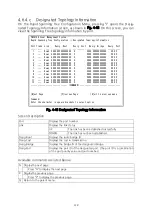
On the Rapid Spanning Tree Configuration Menu, pressing "I" opens the Desig
-
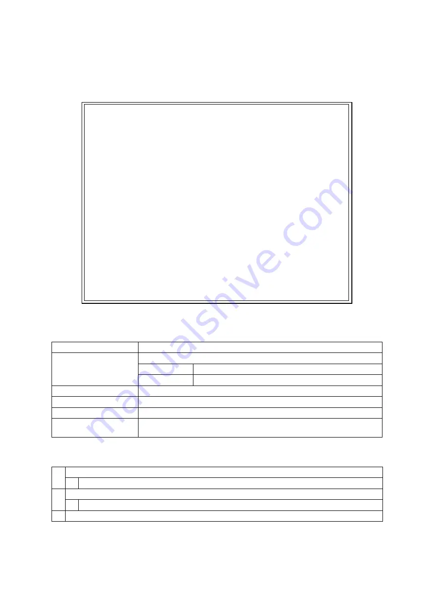
nated Topology Information screen, as shown in Fig. 4-48. On this screen, you can
view the Spanning Tree topology information by port.
PN28168 Local Management System
Rapid Spanning Tree Configuration -> Designated Topology Information
Port Trunk Link Desig. Root Desig. Cost Desig. Bridge Desig. Port
---- ----- ---- ----------------- ----------- ----------------- -----------
1 --- Down 0000 000000000000 0 0000 000000000000 00 00
2 --- Down 0000 000000000000 0 0000 000000000000 00 00
3 --- Down 0000 000000000000 0 0000 000000000000 00 00
4 --- Down 0000 000000000000 0 0000 000000000000 00 00
5 --- Down 0000 000000000000 0 0000 000000000000 00 00
6 --- Down 0000 000000000000 0 0000 000000000000 00 00
7 --- Down 0000 000000000000 0 0000 000000000000 00 00
8 --- Down 0000 000000000000 0 0000 000000000000 00 00
9 --- Down 0000 000000000000 0 0000 000000000000 00 00
10 --- Down 0000 000000000000 0 0000 000000000000 00 00
11 --- Down 0000 000000000000 0 0000 000000000000 00 00
12 --- Down 0000 000000000000 0 0000 000000000000 00 00
-------------------------------- <COMMAND> -----------------------------------
[N]ext Page [P]revious Page [Q]uit to previous menu
Command>
Enter the character in square brackets to select option
Fig. 4-48 Designated Topology Information
Screen Description
Port
Displays the port number.
Link
Displays the link status.
UP
The link has been established successfully.
DOWN
The link has not been established.
Desig.Root
Displays the route bridge ID.
Desig.Cost
Displays the cost in transmission.
Desig.Bridge
Displays the bridge ID of the designated bridge.
Desig.Port
Displays the port ID of the designated port. (The port ID is a combination
of the port priority value and port number.)
Available commands are listed below.
N
Display the next page.
Press "N" to display the next page.
P
Display the previous page.
Press "P" to display the previous page.
Q
Return to the parent menu.


