PAN9420
Fully Embedded Stand-Alone Wi-Fi Module
Product Specification
Rev. 1.1
Wireless Modules
Страница 1: ...PAN9420 Fully Embedded Stand Alone Wi Fi Module Product Specification Rev 1 1 Wireless Modules ...
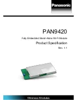
Страница 2: ...file Programming via standard JTAG Evaluation kit with pre installed web application for quick prototyping available Evaluation and development tool WiFigurator for Windows Getting started tutorials PC tool quickstart guide Wide temperature range of 40 C to 85 C Characteristics Surface Mount Type SMT 29 0 mm x 13 5 mm x 2 66 mm Marvell 88MW300 MCU WLAN System on Chip SoC inside Tx power up to 16 d...
Страница 3: ...ly or fully functional and they may differ from the published Product Specification Engineering Samples are not qualified and they are not to be used for reliability testing or series production Disclaimer The customer acknowledges that samples may deviate from the Product Specification and may bear defects due to their status of development and the lack of qualification mentioned above Panasonic ...
Страница 4: ...ion 14 3 1 Dimensions 14 3 2 Footprint 15 3 3 Packaging 16 3 4 Case Marking 19 4 Specification 20 4 1 Default Test Conditions 20 4 2 Absolute Maximum Ratings 20 4 3 Recommended Operating Conditions 21 4 4 RF Electrical Characteristics 29 4 5 Reliability Tests 33 4 6 Recommended Soldering Profile 34 5 Cautions Life Support Policy RoHS Declaration and Regulatory Information 35 5 1 Cautions 35 5 2 Li...
Страница 5: ...01 02 2017 1st preliminary version 0 2 31 05 2017 Improved layout 1 0 02 06 2017 Technical data corrected 1 1 19 06 2017 FCC IC RED information added 1 3 Use of Symbols Symbol Description Note Indicates important information for the proper use of the product Non observance can lead to errors Attention Indicates important notes that if not observed can put the product s functionality at risk chapte...
Страница 6: ...pages or image data Parallel support of access point and infrastructure mode allows easy setup of simultaneous Wi Fi connections from the module to smart devices and home network routers The pre programmed Wi Fi SoC firmware enables client STA micro access point uAP and Ad hoc mode Wi Fi Direct applications With the transparent mode raw data can be sent from the UART to the air interface to smart ...
Страница 7: ... 1 Block Diagram Chip Antenna SPDT 88MW300 MCU Radio SoC Crystal 32 768 kHz QSPI Flash 32 Mbit SPI UART0 UART1 GPIOs Status LEDs MCU Ready Resetn Factory Reset V SPDT Wake Ups JTAG Vcc 3 3 V LPF RF Pad PAN9420 Fully Embedded Wi Fi Module IEEE 802 11 b g n Crystal 38 4 MHz ...
Страница 8: ...C NC Do not connect 7 3 3 V Power 3 0 V 3 6 V power supply connection typical 3 3 V 8 3 3 V Power 3 0 V 3 6 V power supply connection typical 3 3 V 9 UART1 CTS Digital In CTSn for UART1 using hardware flow control 10 UART1 RTS Digital Out RTSn for UART1 using hardware flow control 11 UART1 TXD Digital Out TXD for UART1 12 UART1 RXD Digital In RXD for UART1 13 NC NC Do not connect 14 GND Ground Pin...
Страница 9: ... Digital I O Digital I O 48 31 GPIO471 Digital I O Digital I O 47 32 GPIO461 Digital I O Digital I O 46 33 STAT LED1 Digital Out Connect to LED MCU status heartbeat active low 34 STAT LED2 Digital Out Connect to LED IP connectivity allocated IP active low 35 STAT LED3 Digital Out Connect to LED Error active during booting active low 36 GND Ground Pin Connect to ground 37 RESETn Digital In Reset MC...
Страница 10: ...shing in production process D2 TRSTn Digital In TRSTn for JTAG option for flashing in production process D3 NC NC Do not connect D4 NC NC Do not connect D5 NC NC Do not connect E1 TDO Digital Out TDO for JTAG option for flashing in production process E2 TCK Digital Out TCK for JTAG option for flashing in production process E3 TMS Digital I O TMS for JTAG option for flashing in production process E...
Страница 11: ...format LSB first Data bit 5 8 bit Parity bit 0 3 bit Stop bit 1 2 bit Further information 4 3 7 Host Interface Specification 2 4 Peripheral Bus Interface Embedded MCU and WLAN Radio SoC Features Characteristics JTAG Standard JTAG interface General Purpose I O GPIO Interface Defined GPIOs I O configured to either input or output on off GPIOs with LED status functionality ready heartbeat IP connecti...
Страница 12: ...g IEEE Power Save mode Wi Fi direct connectivity 3 WLAN MAC Simultaneous peer to peer and Infrastructure Modes RTS CTS for operation and DCF Hardware filtering of 32 multicast addresses On chip Tx and Rx FIFO for maximum throughput Open System and Shared Key Authentication services A MPDU RX de aggregation and TX aggregation Reduced Inter Frame Spacing RIFS bursting Management information base cou...
Страница 13: ...ndwidth Embedded WLAN Radio SoC with the following features Direct conversion radio no need for external SAW filter 2 4 GHz TX RX switch Power Amplifier PA and Low Noise Amplifier LNA path Gain selectable LNAs with optimized noise figure and power consumption Power Amplifiers with power control Optimized TX gain distribution for linearity and noise performance Fine channel step with AFC adaptive f...
Страница 14: ...scription Product Specification Rev 1 1 Page 14 29 13 50 2 66 3 Detailed Description 3 1 Dimensions All dimensions are in millimeters No Item Dimension Tolerance Remark 1 Width 13 50 0 35 2 Length 29 00 0 35 3 Height 2 66 0 20 with case ...
Страница 15: ... PAN9420 Wi Fi Module 3 Detailed Description Product Specification Rev 1 1 Page 15 3 2 Footprint The outer dimensions have a tolerance of 0 35 mm ...
Страница 16: ...ction status product and will be delivered in the package described below 3 3 1 Tape Dimensions 3 3 2 Packing in Tape Empty spaces in the component packed area shall be less than two per reel and those spaces shall not be consecutive The top cover tape shall not be found on reel holes and it shall not stick out from the reel ...
Страница 17: ... PAN9420 Wi Fi Module 3 Detailed Description Product Specification Rev 1 1 Page 17 3 3 3 Component Direction 3 3 4 Reel Dimension ...
Страница 18: ...icable Order number Date code Quantity Hardware Software version 3 3 6 Total Package barcode label moisture sensitive print already exist on barrier bag barcode label desiccant 1 2 moisture indicator barrier bag sealed inner carton box size 340 x 340 x 41 mm 1 quantity of desiccant according to calculation 2 optional desiccant placed into the corner of the barrier bag ...
Страница 19: ...Page 19 3 4 Case Marking Example for PAN9420 FCC version 1 2 3 4 5 6 7 8 9 10 11 Brand name Hardware Software version Engineering Sample optional Model Name ENW number Lot code Serial number WLAN MAC address FCC ID IC Canada Marking for Pin 1 2D barcode for internal usage only ...
Страница 20: ...circumstances not even momentarily or individually as permanent damage to the module may result Symbol Parameter Condition Min Typ Max Units TSTOR Storage temperature 40 85 C VESD ESD robustness All pads according to human body model HBM JEDEC STD 22 method A114 1 000 V According to charged device model CDM JEDEC STD 22 method C101 500 V PRF RF input level 20 dBm VDDMAX Maximum voltage Maximum pow...
Страница 21: ...tage5 3 3 V operation VIO VDD 0 4 0 3 VDD V IOH VDD 0 5 V High level output current5 3 3 V operation VIO VDD 3 mA IOL 0 4 V Low level output current5 3 3 V operation VIO VDD 4 mA 4 3 2 Module Selectable RF In Output Module RF Output can be switched between on board ceramic chip antenna and 50 Ohm RF pad pin 16 output by adjusting voltage level on pin A4 and A5 If pin A4 and A5 are not con nected N...
Страница 22: ...ut no active decoding 75 mA IShut off Shut off MCU and Radio in shut off mode 1 mA 4 3 4 Internal Operating Frequencies Symbol Parameter Condition Min Typ Max Units fSYSCLK1 CPU System Encryption clock speed 200 MHz fREFCLK1 WLAN MCU Crystal fundamental frequency Frequency tolerance 10 ppm over operating temperature and process 38 4 MHz fREFCLK2 Sleep Clock Crystal fundamental frequency Frequency ...
Страница 23: ...AKE UP Time period needed to set pin active to wake up from shut off mode afterwards firmware is booting 100 ms T FACTORY RESET Time period needed to set pin active to release factory reset afterwards firmware is booting 8 10 sec T INFRA ASSO Time period in Infrastructure mode from WLAN association request until association with selected Access Point s SSID 4 sec T DE ASSO SCAN Time period between...
Страница 24: ...tput 28 UART0 RXD Receive data input Protocol Item Range Default Comment Baud rate 300 1 500 000 115 200 Baud Data bits 5 8 LSB first 8 LSB first Parity bits 0 3 0 Even odd or no parity detection Stop bit 1 2 1 Supported Baud Rates Baud 300 600 1 200 2 400 4 800 9 600 14 400 19 200 28 800 38 400 56 000 57 600 115 200 128 000 256 000 520 000 780 000 1 500 000 UART0 Timing Diagram Start Data bits 5 ...
Страница 25: ...e data input Protocol Item Range Default Comment Baud rate 300 1 500 000 115 200 Baud Data bits 5 8 LSB first 8 LSB first Parity bits 0 3 0 Even odd or no parity detection Stop bit 1 2 1 Supported Baud Rates Baud 300 600 1 200 2 400 4 800 9 600 14 400 19 200 28 800 38 400 56 000 57 600 115 200 128 000 256 000 520 000 780 000 1 500 000 UART1 Timing Diagram Data bits Data bits Clear to send Clear to...
Страница 26: ... MCU READY pin changes from low level to high level As start condition the DUAL SW input pin needs to be pre set from the HOST by changing from high level to low level The DUAL STAT output pin signals high level as Binary state In this case the HOST is able to transmit or receive binary data To change from Binary to Command state the DUAL SW input pin needs to be toggled low high low level change ...
Страница 27: ...ES YES YES YES Output OUT ON YES YES YES YES YES YES OFF YES YES YES YES YES YES Default by firmware OFF OUT OUT OUT OUT OUT OUT The functions of the configurable GPIOs are set by the firmware Default Config but they can be reconfigured by using the HOST command interface UART Booting Default Default Ready state Binary state Command state Binary state Clear Clear Command Binary Request Request MCU...
Страница 28: ...or W STAT LED NO YES LOW OFF OFF no AP connection BLINK 0 2 s Scanning for AP BLINK 0 4 s trying to connect to AP BLINK 1 2 s WLAN Error ON Associated with AP WLAN connectivity in Infrastructure mode MCU READY NO YES HIGH OFF OFF Shut off ON Firmware ready Firmware application is ready FACTORY RESET YES NO LOW 10 HIGH inactive Set active for min 10 seconds Restore firmware default WAKE UP0 YES NO ...
Страница 29: ...1b 5 5 11 Mbps DSSS CCK Supported data rates IEEE 802 11g 6 9 12 18 24 36 48 54 Mbps IEEE 802 11n MCS0 7 HT20 LGI 6 5 13 19 5 26 39 52 58 5 65 Mbps SGI 7 2 14 4 21 7 28 9 43 3 57 8 65 72 2 Mbps Supported bandwidth IEEE 802 11n 20 MHz BW Supported Guard Interval IEEE 802 11n 400 ns SGI 800 ns LGI Supported channel 2 4GHz11 IEEE 802 11 b g n North America US 1 2 3 4 5 6 7 8 9 10 11 Canada CA 1 2 3 4...
Страница 30: ...in Typ Max Units RF frequency range 2 400 2 483 5 MHz Carrier frequency tolerance 25 25 ppm Transmit output power 16 18 dBm Spectrum mask fC 11 MHz 30 dBr fC 22 MHz 50 Power on Power down ramp 2 µs RF Carrier suppression 15 dB Error Vector Magnitude EVM Peak 35 Minimum Receive Sensitivity 1 Mbps DSSS FER 8 97 86 dBm 2 Mbps DSSS FER 8 94 83 dBm 5 5 Mbps CCK FER 8 91 79 dBm 11 Mbps CCK FER 8 88 76 d...
Страница 31: ...l Flatness 2 2 dB Constellation Error EVM BPSK CR 1 2 6 Mbps 5 dB BPSK CR 3 4 9 Mbps 8 dB QPSK CR 1 2 12 Mbps 10 dB QPSK CR 3 4 18 Mbps 13 dB 16 QAM CR 1 2 24 Mbps 16 dB 16 QAM CR 3 4 36 Mbps 19 dB 64 QAM CR 2 3 48 Mbps 22 dB 64 QAM CR 3 4 54 Mbps 25 dB Minimum Receive Sensitivity BPSK CR 1 2 6 Mbps PER 10 90 82 dBm BPSK CR 3 4 9 Mbps PER 10 89 81 dBm QPSK CR 1 2 12 Mbps PER 10 87 79 dBm QPSK CR 3...
Страница 32: ...lation Error EVM BPSK CR 1 2 MCS0 5 dB QPSK CR 1 2 MCS1 10 dB QPSK CR 3 4 MCS2 13 dB 16 QAM CR 1 2 MCS3 16 dB 16 QAM CR 3 4 MCS4 19 dB 64 QAM CR 2 3 MCS5 22 dB 64 QAM CR 3 4 MCS6 25 dB 64 QAM CR 5 6 MCS7 27 dB Minimum Receive Sensitivity12 6 5 Mbps MCS0 PER 10 90 82 dBm 13 Mbps MCS1 PER 10 87 79 dBm 19 5 Mbps MCS2 PER 10 85 77 dBm 26 Mbps MCS3 PER 10 82 74 dBm 39 Mbps MCS4 PER 10 79 70 dBm 52 Mbps...
Страница 33: ...cal parameter should be in specification Freq 20 2 000 Hz 17g 50g cycle 2 hrs each of XYZ axis 2 Shock test the same as above Dropped onto concrete from a height of 1 m for 3 times 3 Heat shock cycle test the same as above 50 C for 30 min and 125 C for 300 cycles each 15 min 4 Temperature humidity bias test THB the same as above 85 C 85 RH 500 h 5 Low temp storage test LTST the same as above 40 C ...
Страница 34: ... Profile Reflow permissible cycle 2 Opposite side reflow is prohibited due to module weight More than 75 percent of the soldering area shall be coated by solder The soldering profiles should be adhered to in order to prevent electrical or mechanical damage Soldering profile assumes lead free soldering ...
Страница 35: ...um tolerance 6 The supply voltage should not be exceedingly high or reversed It should not carry noise and or spikes 7 Keep this product away from other high frequency circuits 5 1 2 Installation Notes 1 Reflow soldering is possible twice based on the conditions in 4 6 Recommended Soldering Profile Set up the temperature at the soldering portion of this product according to this reflow profile 2 C...
Страница 36: ...l electronic equipment such as home appliances office equipment information and communication equipment 5 1 4 Storage Notes 1 The module should not be stressed mechanically during storage 2 Do not store these products in the following conditions or the performance characteristics of the product such as RF performance will be adversely affected Storage in salty air or in an environment with a high ...
Страница 37: ... 3 Be sure to provide an appropriate fail safe function on your product to prevent an additional damage that may be caused by the abnormal function or the failure of the product 4 This product has been manufactured without any ozone chemical controlled under the Montreal Protocol 5 These products are not intended for uses other than under the special conditions shown below Before using these produ...
Страница 38: ...vironmental compatibility RoHS and REACH for supplied products can be found on the Panasonic website in the Downloads section of the respective product 6 2 2 Product Information 5 4 Regulatory Information 5 4 1 FCC for US 5 4 1 1 FCC Notice The PAN9420 including the ceramic antenna ENW49C01A3KF and including the antennas which are listed in 5 4 1 5 Approved Antenna List complies with Part 15 of th...
Страница 39: ...to which the receiver is connected Consult the dealer or an experienced radio TV technician for help 5 4 1 3 Label Requirements The Original Equipment Manufacturer OEM must ensure that FCC labelling requirements are met This includes a clearly visible label laser marking on the outside of the OEM enclosure specifying the appropriate Panasonic FCC identifier for this product as well as the FCC Noti...
Страница 40: ...n of the module is restricted to mobile host devices Nevertheless the PAN9420 shall be used in such a manner that the potential for human contact during normal operation is minimized End users may not be provided with the module installation instructions OEM integrators and end users must be provided with transmitter operating conditions for satisfying RF exposure compliance 5 4 2 Industry Canada ...
Страница 41: ...cune circonstance être utilises en combinaison avec ce produit L impédance des antennes compatibles est 50 Ohm L antenne utilisée avec ce produit ne doit ni être située à proximité d une autre antenne ou d un autre émetteur ni être utilisée conjointement avec une autre antenne ou un autre émetteur 5 4 2 1 IC Notice English The device PAN9420 and versions 6 1 Ordering Information including the ante...
Страница 42: ...s 6 1 Ordering Information In any case the end product must be labelled on the exterior with Contains IC 216Q 9420 French Obligations d étiquetage Les fabricants d équipements d origine FEO en anglais Original Equipment Manufacturer OEM doivent s assurer que les obligations d étiquetage IC du produit final sont remplies Ces obligations incluent une étiquette clairement visible à l extérieur de l e...
Страница 43: ... V3 1 1 2017 02 3 2 Radio EN 300 328 V2 1 1 2016 11 As a result of the conformity assessment procedure described in 2014 53 EU Directive the end customer equipment should be labelled as follows The end customer has to assure that the device has a distance of more than 20 cm from the human body under all circumstances The end customer equipment must meet the actual Safety Health requirements accord...
Страница 44: ...rant IDs marked on the module labelling are referenced and only valid if the ceramic on board chip antenna on module is used 16 The model with the Regulatory Domain FCC IC M N ENW49C01A3KF is only intended to be used in the countries of US and Canada because only the channels 1 11 2412 2462 MHz are supported in the 2 4 GHz ISM band It is not possible to change the pre stored Region Code in order t...
Страница 45: ...rica visit the Panasonic Sales Support Tool to find assistance near you at https na industrial panasonic com distributors Please visit the Panasonic Wireless Technical Forum to submit a question at https forum na industrial panasonic com 6 2 2 Product Information Please refer to the Panasonic Wireless Connectivity website for further information on our products and related documents For complete P...