PAN1780 Bluetooth Module
5 Getting Started
Module Integration Guide Rev. 1.1
Page 21 of 44
5
Getting Started
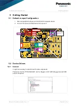
5.1 Default Jumper Configuration
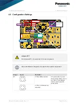
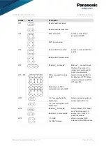
Place all highlighted jumpers on PAN1780 ETU Evaluation Board.
1.
Connect the device via USB (Socket X2) to power it.
2.
5.2 Device Drivers
5.2.1 General
It might be necessary to install drivers for some components.
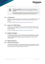
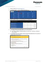
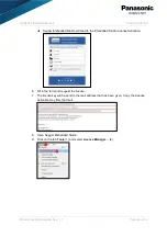
Please note that the “FTDI USB UART” and the “Segger J-Link” SWD debugger provide COM
ports to the system.
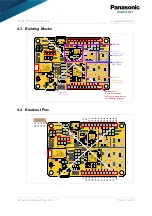
3.3V to pin
Do not place
with external 3.3V supply
5V from USB
5V from pin
Module VCC
Switch Module UART:
Breakout pins
FTDI
SWD
Module Reset
UART
Module VCC5V Breakout
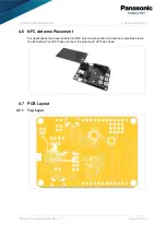
NFC Antenna
Содержание PAN1780
Страница 1: ...Wireless Connectivity PAN1780 Bluetooth Low Energy Module Module Integration Guide Rev 1 1 ...
Страница 14: ... PAN1780 Bluetooth Module 4 Reference Design Module Integration Guide Rev 1 1 Page 14 of 44 4 2 Schematic ...
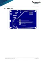
Страница 20: ... PAN1780 Bluetooth Module 4 Reference Design Module Integration Guide Rev 1 1 Page 20 of 44 4 7 4 Bottom Layer ...

