


When ordering the above procedure, setting of the model code, option code, tuning channel can
be skipped. / However, all electrical adjustment data is unique value in accordance with a deck,
perform the Electrical Adjustment continuously.
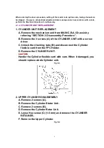
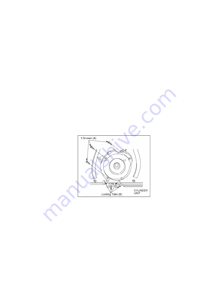
2.1.2. CYLINDER UNIT REPLACEMENT
1. CYLINDER UNIT REPLACEMENT
A. Remove the mechanism unit from MAIN C.B.A./Chassis by
referring “SECTION 2. Disassembly Procedure”.
B. Remove the 3 screws (A) of the CYLINDER UNIT with a screw
driver.
C. Unlock the 4 locking tabs (B) and disconnect the Cylinder
fiexible card from the FPC Holder.
D. Remove the CYLINDER UNIT.
CAUTION:
Handle the Cylinder fiexible card with care. When it damaged, you
should replace whole Cylinder unit.
Fig. S3
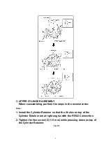
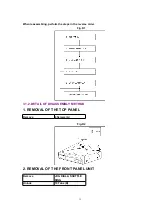
2. UPPER CYLINDER DISASSEMBLY
A. Remove 2 screws (A).
B. Remove the Cylinder Stator Unit.
C. Remove 2 screws (B).
D. Remove the Cylinder Rotor Unit.
E. Loose Hex screw (C) (1.5 mm) and remove the CYLINDER
RETAINER.
F. Remove the Upper Cylinder.
Fig. S4
5
Содержание NV-HS825EG
Страница 22: ...3 3 8 CIRCUIT BOARD LAYOUT 22 ...
Страница 25: ...10 2 CASING PARTS SECTION 25 ...
Страница 26: ...10 3 PACKING PARTS SECTION 26 ...
Страница 27: ...11 REPLACEMENT PARTS LIST 11 1 CHASSIS PARTS SECTION PARTS LIST 27 ...
Страница 42: ...L7601 VLQ0599J330 COIL 33UH G0C330JA0026 42 ...
Страница 83: ...PS4801 A 1 FRONT C B A Connector ADDRESS INFORMATION NV HS825EG B EC FRONT C B A VEP04782B 1 A C B 3 2 4 ...
Страница 85: ... VEP06E13A NV HS825EG B EC JOG C B A 1 A C B D 3 2 PS6301 A 3 JOG C B A Connector ADDRESS INFORMATION ...


