16
6 Disassembly and Assembly Instructions
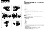
For assembly, refer to the Assembly Instructions, and perform the procedures in the opposite order of disassembly.
6.1.
Attachment
1. Remove the Fixing lever for removal of the Grinder head
section.
6.2.
Storage part for attachment
1. Storage part for attachment in the body rear is drawn out
and removed from the Body ass'y.
6.3.
Lid of cord storage
1. Lift the Lid of cord storage, decide to push a hinge part of
a lid inside and remove a lid from the Body ass'y.
2. Power cord is drawn out.
6.4.
Switch knob
1. The body stave, and remove the Switch Knob using a
minus driver.
Содержание MK-ZJ3500KTN
Страница 2: ...2 1 Safety Precautions ...
Страница 3: ...3 2 Specifications 2 1 Specifications MK ZJ3500 MK ZJ2700 2 2 Important Information ...
Страница 4: ...4 3 Location of Controls and Components ...
Страница 5: ...5 ...
Страница 6: ...6 4 Operating Instructions 4 1 How to use ...
Страница 7: ...7 ...
Страница 8: ...8 ...
Страница 9: ...9 ...
Страница 10: ...10 4 2 After use ...
Страница 11: ...11 ...
Страница 12: ...12 4 3 Troubleshooying Circuit Breaker Protection ...
Страница 14: ...14 5 8 Check point MK ZJ3500 ...
Страница 15: ...15 MK ZJ2700 ...
Страница 20: ...20 7 Wiring Connection Diagram 7 1 Actual wiring diagram MK ZJ3500 ...
Страница 21: ...21 MK ZJ2700 ...
Страница 22: ...22 7 2 Wiring processing figure MK ZJ3500 ...
Страница 23: ...23 MK ZJ2700 ...
Страница 24: ...24 8 Schematic Diagram 8 1 Circuit diagram MK ZJ3500 ...
Страница 25: ...25 MK ZJ2700 ...
Страница 26: ...26 9 Exploded View and Replacement Parts List 9 1 Parts Exploded View MK ZJ3500 ZJ2700 Body ...


