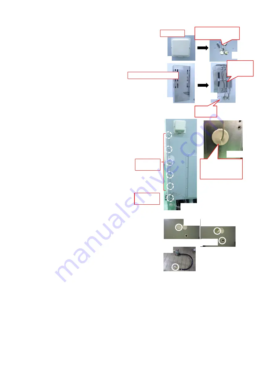
⑩
⑪
⑫
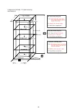
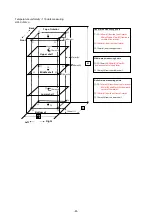
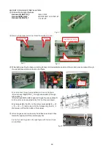
Fill the gap between sensor insertion hole and gas thermo with
silicon.
Reinstall the temperature control sensor cover and the sensor
outlet cover.
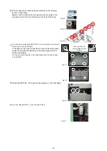
Remove the sensor outlet cover on the back and the temperature
control sensor cover inside the chamber, and remove the silicone
in the backup sensor insertion hole.
Insert the gas thermo into the backup sensor insertion hole from
which silicon has been removed and fix the gas thermo using the
nylon clip attached to the sensor mounting plate.
Attach the nylon clips SL - 2 N and SL - 6
N to the holes for those on the back and
secure the gas thermo piping with them.
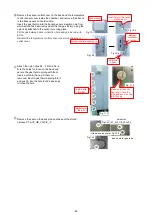
Insert a notch in the cap A that you
removed, insert a gas thermo piping into it,
and push A into the hole in the base so as
to close the hole.
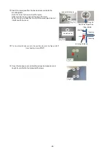
Remove the seal on the back side and take out the stored
harness PT_AIP_UB_VALVE_ 2.
seal with
silicon
Cation:
installation
direction
censor cover
thermal control sensor cover
insert hole for the censor
of back-up kit
nylon crip
SL-6N
make an incision the
cap, insert it into the
pipe, and push the cap
into the hole
nylon crip
SL-2N
insert hole for gas tube
solenoid valve power
harnesses
PT_AIP_UB_VALVE_2
Fig.10-1
Fig.10-2
Fig.10-3
Fig.10-4
Fig.11-1
Fig..11-2
Fig.12-1
Fig.12-2
Fig.12-3
-68-
Содержание MDF-DU702VH
Страница 8: ...Dimension MDF DU502VH 5 ...
Страница 9: ...MDF DU702VH 6 ...
Страница 17: ...Wiring Diagram 14 ...
Страница 18: ...main Circuit Diagram 15 ...
Страница 19: ...power 16 ...
Страница 20: ...USB 17 ...
Страница 73: ...WIRING YG Y Y GR B G W W W Y G R BL Y W R R BL R OR B BL R OR B Y W Y G Y G R BL 70 ...

