


48
Installing connector cover to cable
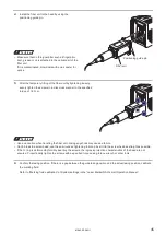
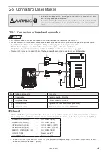
To ensure the ingress protection (IP64) of the head, install the attached connector cover to the unit power cable and signal
cable.
ワㄐㄕㄊㄆ
• If there are signs of deterioration or damage in the gaskets of the connector covers, replace them. Replacement
connector covers and gasket (LP-ACC10) are available on request. For purchasing them, contact our sales agency.
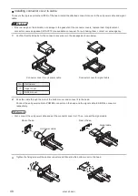
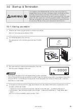
1.
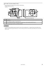
Confirm that the all parts for the connector covers are in the package as shown below.
w
q
w
q
Connector cover for unit power cable
Connector cover for signal cable
No.
Part name
q
Upper cover
w
Bottom cover
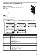
2.
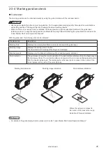
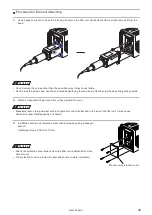
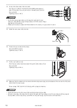
Pass the cable through the hole of the bottom cover and connect it to the head.
Connect the unit power cable to POWER connector on the head and the signal cable to SIGNAL connector
respectively.
ンㄆㄇㄆㄓㄆㄏㄆ
• First, connect the unit power cable and set the connector cover to it. Then, connect the signal cable.
Unit power cable
Signal cable
Rear of head
Rear of head
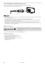
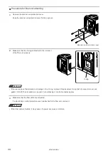
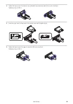
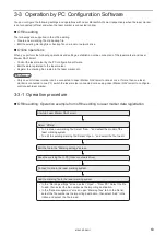
3.
Tighten the fixing screw of the cable connector and then slide the bottom cover to the head.
ME-LPRF-SM-11
Содержание LP-RF Series
Страница 17: ...1 Product Overview ME LPRF SM 11...
Страница 34: ...2 Laser Marker Installation ME LPRF SM 11...
Страница 57: ...3 Operation Method ME LPRF SM 11...
Страница 81: ...4 External Control Using I O ME LPRF SM 11...
Страница 126: ...5 External Control by Communication Commands ME LPRF SM 11...
Страница 135: ...6 Link Control with External Devices ME LPRF SM 11...
Страница 160: ...7 Maintenance ME LPRF SM 11...
Страница 186: ...Troubleshooting ME LPRF SM 11...
Страница 214: ...Index ME LPRF SM 11...
Страница 216: ...216 USB 32 55 W Warning 205 ME LPRF SM 11...
Страница 217: ......


