– 94 –
Chapter 5 Basic Operations — Video memory
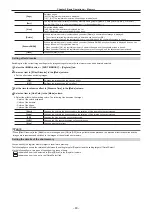
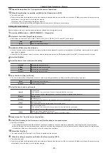
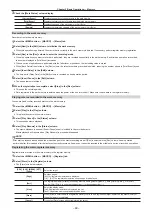
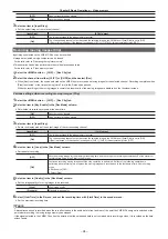
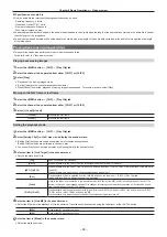
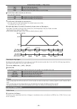
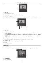
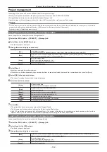
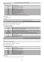
[OFF]
Does not record the key signals.
[ON]
Records the key signals.
3
Select an item in [Input Disp].
f
Set the output image of the relevant channel.
[Input Disp]
[STILL] output
[OFF]
The image recorded in the video memory is output.
[ON]
The corresponding channel output becomes the selected image in the VMEM bus if [Input Disp] is set to [ON].
If [Capture] is pressed or if the channel is changed in [STILL1], [STILL2], this automatically turns [OFF].
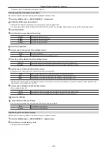
Recording moving images (Clip)
Input images selected on the VMEM F/S bus can be recorded.
f
Image data created using a computer can be loaded.
For details, refer to “Operating the register memory”.
f
This operation can be also performed in the multi-selection panel area.
For details, refer to “Video memory menu”.
1
Select the <MEM> button
→
[CLIP]
→
[Rec Clip] tab.
2
Select the channel from either [CLIP1] or [CLIP2] and then select [Rec].
f
When [Rec] is selected, the source selected on the VMEM bus is recorded as moving images for the selected channel. Recording completes when
[Stop] is selected, or the time set using [Limit Time] in the R menu has passed.
When the recording of the moving images is completed, thumbnails of the moving images are displayed on the thumbnail screen.
Various settings when recording moving images (Clip)
1
Select the <MEM> button
→
[CLIP]
→
[Rec Clip] tab.
2
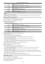
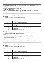
Select an item in [Key Enable] in the [Rec Mode] column.
f
Set whether to record key signals at the same time.
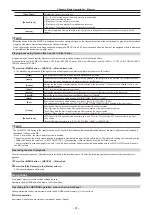
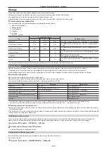
[ON]
Records the key signals.
[OFF]
Does not record the key signals.
3
Select an item in [Input Disp].
f
Switch the display mode of the output image of the corresponding channel.
[Input Disp]
[CLIP] output
[OFF]
The image recorded in the video memory is output.
[ON]
The corresponding channel output becomes the selected image in the VMEM bus if [Input Disp] is set to [ON].
If [Rec] is pressed or if the channel is changed in [CLIP1], [CLIP2], this automatically turns [OFF].
4
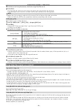
Select an item in [Loop] in the [Rec Mode] column.
f
Set repeat of recording.
[OFF]
Records moving images for the maximum recording time, and then stops the recording automatically. Set the maximum
recording time using [Limit Time] in the R menu.
[ON]
Continues recording moving images until the stop operation is performed. If either of the following operations is
performed while recording is in progress, the moving images are recorded up to the last frame, after which recording
stops.
f
Set [Loop] to [OFF].
f
Select [Stop].
5
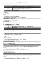
Select an item in [Quality] in the [Rec Mode] column.
f
Set the image quality of moving images to be recorded.
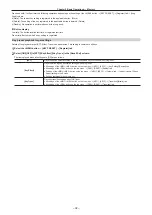
[High]
High image quality
[Standard]
Standard image quality
6
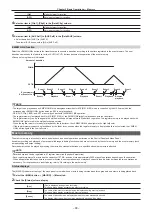
Select [Limit Time] in the R menu, and set the recording time with [Limit Time] in the encoder menu.
f
Set the maximum recording time.
@
@
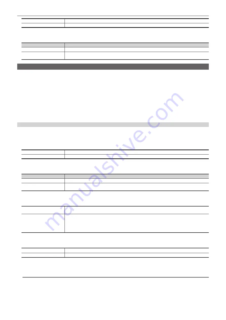
NOTE
t
A discontinued sound is recorded when there is a fluctuation in the audio data in front and rear of the point the VMEM F bus signal is switched or the
point where recording to moving image memory has stopped.
t
If the signal selected in the VMEM F bus has the duration that the embedded data is not contained while recording a video, it is recorded as the data
without audio.
Содержание Live Production Suite Series
Страница 5: ...Please read this chapter and check the accessories before use Chapter 1 Overview ...
Страница 11: ...This chapter describes installation and connection Chapter 2 Installation and Connection ...
Страница 33: ...This chapter describes basic operations and matters to be performed prior to use Chapter 4 Preparations ...
Страница 50: ...This chapter describes menu operations Chapter 5 Basic Operations ...
Страница 107: ...This chapter describes the input output signal settings Chapter 6 Input Output Signal Settings ...
Страница 112: ... 112 Chapter 6 Input Output Signal Settings Setting MultiView displays f f Set the marker size ...
Страница 113: ...This chapter describes the configuration of operations Chapter 7 Configuring Operations ...
Страница 122: ...This chapter describes how to operate system menus Chapter 8 System Menu ...
Страница 136: ...This chapter describes plug in functions Chapter 9 External Interfaces ...
Страница 138: ...This chapter describes the dimensions and specifications of this product Chapter 10 Specifications ...
Страница 139: ... 139 Chapter 10 Specifications Dimensions Dimensions Dimensions of the Gateway Unit AV LSG10 Unit mm inch ...
Страница 140: ... 140 Chapter 10 Specifications Dimensions Dimensions of the XPT Unit AV LSX10 Unit mm inch ...
Страница 141: ... 141 Chapter 10 Specifications Dimensions Dimensions of the ME Unit AV LSM10 Unit mm inch ...
Страница 142: ... 142 Chapter 10 Specifications Dimensions Dimensions of the System Manager Unit AV LSS10 Unit mm inch ...
Страница 153: ...This chapter describes the setting menu table and terms Chapter 11 Appendix ...
Страница 176: ...Web Site https www panasonic com Panasonic Corporation 2020 ...

