– 77 –
Chapter 5 Basic Operations — Switching the AUX output
Switching the AUX output
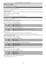
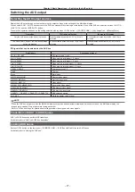
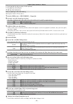
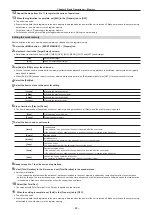
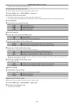
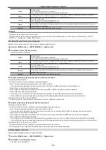
Selecting the AUX output sources
Display the AUX output image on the monitor using the output settings or the settings of the MultiView display.
You can select AUX1 - AUX16 bus sources in the AUX bus crosspoint by pressing a combination of one of the AUX bus selection buttons <AUX 1/2> -
<AUX 15/16> and the <BUS SHFT> button.
The selection operation depends on the setting selected with top menu <OPR> button
→
[SOURCE LINK]
→
[Key Assign] tab
→
[Master/Slave].
Operation
[Fill to Source] setting
[Source to Fill] setting
Only the AUX bus selection button is pressed
Odd numbered buses from AUX1 - AUX15 are
selected
Even numbered buses from AUX2 - AUX16 are
selected
The <BUS SHFT> button
+
the AUX bus selection
button are pressed
Even numbered buses from AUX2 - AUX16 are
selected
Odd numbered buses from AUX1 - AUX15 are
selected
r
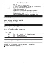
Signals that can be selected on the AUX bus
Signal name
Description of signal
SDI IN1 - SDI IN20
SDI input signals 1 to 20
Still 1V, Still 2V
Video memory (still image) 1, 2 videos
Still 1K, Still 2K
Video memory (still image) 1, 2 keys
Clip 1V, Clip 2V
Video memory (moving image) 1, 2 videos
Clip 1K, Clip 2K
Video memory (moving image) 1, 2 keys
CBGD1, CBGD2
Color background 1, 2
CBAR
Color bar
Black
Black image
ME1PGM, ME2PGM
Program video signal
ME1PVW, ME2PVW
Preview video signal
ME1CLN, ME2CLN
Clean signal
ME1KEYPVW, ME2KEYPVW
Key preview video signal
DSKPGM1, DSKPGM2
DSK program video signal
DSKPVW1, DSKPVW2
DSK preview video signal
DSKEXT1-1, DSKEXT1-2, DSKEXT2-1, DSKEXT2-2
DSK extended signals
MV1, MV2
MultiView display output signal
@
@
NOTE
t
When the AUX bus image for which the MultiView display output has been selected is displayed on the sub-screen of the MultiView display, the
images are looped as if two mirrors were facing each other.
t
Refer to “ME unit settings” for details about setting preview video signals and clean signals.
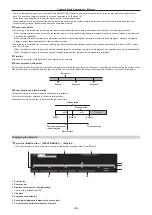
Transitions of AUX1 to AUX4 buses
AUX1 to AUX4 buses can perform MIX transitions.
For details, refer to “AUX1 to AUX4 bus transitions”.
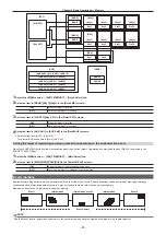
Linking AUX buses
Set the <OPR> button on the top menu
→
[SOURCE LINK]
→
[AUX Bus Link] tab to link two AUX buses.
Содержание Live Production Suite Series
Страница 5: ...Please read this chapter and check the accessories before use Chapter 1 Overview ...
Страница 11: ...This chapter describes installation and connection Chapter 2 Installation and Connection ...
Страница 33: ...This chapter describes basic operations and matters to be performed prior to use Chapter 4 Preparations ...
Страница 50: ...This chapter describes menu operations Chapter 5 Basic Operations ...
Страница 107: ...This chapter describes the input output signal settings Chapter 6 Input Output Signal Settings ...
Страница 112: ... 112 Chapter 6 Input Output Signal Settings Setting MultiView displays f f Set the marker size ...
Страница 113: ...This chapter describes the configuration of operations Chapter 7 Configuring Operations ...
Страница 122: ...This chapter describes how to operate system menus Chapter 8 System Menu ...
Страница 136: ...This chapter describes plug in functions Chapter 9 External Interfaces ...
Страница 138: ...This chapter describes the dimensions and specifications of this product Chapter 10 Specifications ...
Страница 139: ... 139 Chapter 10 Specifications Dimensions Dimensions Dimensions of the Gateway Unit AV LSG10 Unit mm inch ...
Страница 140: ... 140 Chapter 10 Specifications Dimensions Dimensions of the XPT Unit AV LSX10 Unit mm inch ...
Страница 141: ... 141 Chapter 10 Specifications Dimensions Dimensions of the ME Unit AV LSM10 Unit mm inch ...
Страница 142: ... 142 Chapter 10 Specifications Dimensions Dimensions of the System Manager Unit AV LSS10 Unit mm inch ...
Страница 153: ...This chapter describes the setting menu table and terms Chapter 11 Appendix ...
Страница 176: ...Web Site https www panasonic com Panasonic Corporation 2020 ...

