background image

Page 5-26

5-6

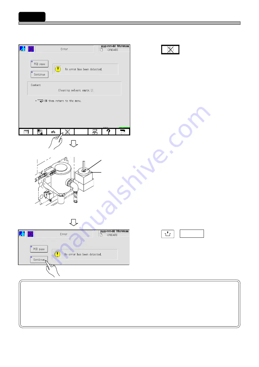
How to Supply Cleaning Solvent

When cleaning solvent is running short, the following screen is displayed with a buzzer and this
machine comes to a cycle stop.

1.

Press 

 .

• The buzzer stops.

2.

Open the lid of the solvent tank, then
supply solvent.

• The tank can hold 2

 l

 of solvent.

3.

Press 

UNLOCK

 +  Continue  .

• After the solvent has been supplied, cleaning is

resumed.

NOTICE

Use IPA or ethyl alcohol as the solvent.
(A mixture of IPA and ethyl alcohol can also be used.)
Never use solvent other than the ones mentioned above.
Otherwise, this machine will be damaged.

193C-EOp-PrEr-001

1B4C-1956C1AD

Lid

Solvent tank

193C-EOp-PrEr-001

1E4C-E-OMA05-A02-00

Содержание KXF-1B4C

Страница 1: ...Thank you for purchasing SP28P the high speed screen printer Before placing the machine in service be sure to read the instruction manual for proper usage After that store it carefully and it if necessary 1E4C E OMAB 0009 High Speed Screen Printer SP28P Operating Manual ...

Страница 2: ......

Страница 3: ... Saga Japan TEL 81 942 84 2644 FAX 81 942 84 2636 For Service and Supply of Spares in Europe you may contact Panasonic Europe Continental Europe PFSE Panasonic Factory Solutions Europe Winsbergring 15 22525 Hamburg Germany Phone number 0049 0 40 85386 321 Fax number 0049 0 40 85386 332 United Kingdom PFSE Panasonic Factory Solutions Europe Panasonic House Willoughby Road Bracknell Berks RG12 8 FP ...

Страница 4: ... t m m 5 0 n o i t a r e l e c c a y t i c o l e v e s a e l e r k s a M l o r t n o c y t i c o l e v m r o f i n u l o r t n o c d e e p s h g i h l o r t n o c e l p i t l u m l o r t n o c n o i t a r e l e c c a s m m 1 0 s m m 5 o t s m m 1 0 y t i c o l e v l a n i m r e t s m m 5 0 0 y t i c o l e v l a i t i n I s m m 0 1 o t s m m 1 0 s m m 5 o t s m m 1 0 s m m 5 o t n o i t c n u f g n...

Страница 5: ...nd person in charge The production data of the line including this machine are programmed on PT Refer to the instruction manuals accompanied with PT Operating manual Manuals of this equipment This manual is for the persons who maintain this equipment It de scribes simple inspection adjustment and replacement of consumable parts Troubleshooting is also described Maintenance manual The assembly of e...

Страница 6: ...4 1E4C E OMA00 B01 00 MEMO ...

Страница 7: ...ng Manual 1E4C E OMA00 A02 13 SAFETY PRECAUTIONS GENERAL DESCRIPTION BASIC OPERATION FUNCTIONS DAILY PRODUCTION SETTING PRODUCTION MATERIALS FILE OPERATION DATA EDITING TEACHING CHANGING PRODUCTION BOARD TYPE CARTRIDGE HEAD APPENDIX ...

Страница 8: ...Keys 2 5 2 2 3 Switch Types and How to Operate 2 7 2 2 4 Messages 2 9 2 3 Main Menu 2 10 2 4 Engineer Mode 2 12 2 4 1 How to Enter Engineer Mode 2 12 2 4 2 How to Change Password 2 13 Chapter 3 FUNCTIONS 3 1 Menu Configuration 3 2 3 1 1 Operator Mode 3 2 3 1 2 Engineer Mode 3 3 3 2 Production Settings 3 5 3 2 1 Squeegee Open Close 3 5 3 2 2 Board Transport 3 6 3 2 3 Mask Cleaning 3 7 3 2 4 Counter...

Страница 9: ...1 Switches for Adjustment 3 27 3 5 2 Setting Time 3 28 3 5 3 Collecting Recognition Result 3 28 3 5 4 Feedback Range 3 29 3 5 5 Feedback History 3 29 3 5 6 Customizing Operator Mode 3 30 Chapter 4 DAILY PRODUCTION 4 1 Production Work Flow 4 2 4 2 Before Starting Production 4 3 4 2 1 Start up Inspection 4 3 4 2 2 Checking Air Pressure 4 4 4 3 Starting Production 4 5 4 3 1 Starting up this Machine 4...

Страница 10: ...n of PT 6 2 6 2 File Operation of Floppy Disk 6 4 6 2 1 How to Save Data 6 5 6 2 2 How to Load Data 6 7 6 2 3 How to Initialize Floppy Disk 6 8 6 2 4 How to Load and Save Machine Parameters 6 10 6 2 5 How to Load Coordinates Data 6 12 6 2 6 How to Load Recognition Data 6 13 6 2 7 How to Delete Data 6 14 Chapter 7 DATA EDITING 7 1 Summary of Data Editing 7 2 7 1 1 Before Data Editing 7 2 7 1 2 Flow...

Страница 11: ...diting CleaningData 7 30 7 10 5 Printing Counter 7 31 7 10 6 Editing Printing Counter 7 32 7 10 7 Library Data 7 33 7 10 8 Returning Printing Conditions Data to Library Data 7 34 7 10 9 Reflecting Printing Conditions Data on Library Data 7 36 7 11 Printing Position Data 7 38 7 11 1 Printing Position Data 7 38 7 11 2 Editing Printing Position data 7 38 7 12 Data Check 7 39 7 12 1 Data Check 7 39 7 ...

Страница 12: ...ng Pressure Teaching 8 22 8 5 3 Teaching Procedure 8 23 8 6 Batch Teaching 8 25 8 6 1 Batch Teaching 8 25 8 6 2 Flowchart of Batch Teaching 8 25 8 6 3 Teaching Procedure 8 25 8 7 Solder Recognition Teaching 8 26 8 7 1 Solder Recognition Teaching 8 26 8 7 2 Flow Chart of Solder Recognition Teaching 8 26 8 7 3 Teaching Procedure 8 27 Chapter 9 CHANGING PRODUCTION BOARD TYPE 9 1 How to Change Product...

Страница 13: ...eration 10 17 10 2 2 Solder Kneading Interruption During Production 10 18 10 3 Removing Setting and Keeping Printing Unit 10 19 10 3 1 Removing the printing unit 10 19 10 3 2 Setting the Printing Unit 10 21 10 3 3 Keeping the Printing Unit 10 23 10 4 Replacing the Cartridge Head and Squeegee 10 25 10 4 1 Replacing to the squeegee from the cartridge head 10 25 10 4 2 Replacing from the Squeegee to ...

Страница 14: ...12 1E4C E OMA00 A02 01 MEMO ...

Страница 15: ...s are only some examples of the symbolic indications This indication refers to a situation which is considered that there is imminent danger of death or serious injury This indication refers to a situation which is considered that there is a possibility of death or serious injury This indication refers to a situation which is considered that there is a possibility of only injury or physical damage...

Страница 16: ...rve 1E4C E XXA00 A03 01 L06EB DO NOT OPEN THE COVER WHEN OPER ATING You will have serious injury if you touch the active part inside DANGER L02E DO NOT TOUCH AC TIVE PART WHEN OPERATING You will have serious injury if you touch the active part ...

Страница 17: ...ur There are two emergency stop buttons Pressing any one of them stops operation Press the nearest one Remove the cause of the danger or abnormality then re start the machine To reset the emergency stop button pull it forward SP28P DH D The explanation by using SP28P DH illustration M33E 2B 1E4C AA00 E MERGEN C Y STOP E MERGEN C Y STOP E M E RGENC Y STO P 1E4C E XXA00 A03 00 WARNING 2 Emergency st...

Страница 18: ...r There are two emergency stop buttons Pressing any one of them stops operation Press the nearest one Remove the cause of the danger or abnormality then re start the machine To reset the emergency stop button pull it forward SP28P DHU DU The explanation by using SP28P DH illustration M33E 2B 1E4C AA00 E MERGEN C Y STOP E MERGEN C Y STOP E M E RGENC Y STO P 1E4C E XXA00 A03 00 WARNING 2 Emergency s...

Страница 19: ... struck by an electric shock There are three levels of procedure shown below for each kind of work For repairing the control box Cutting off the power suly of the machine This is used to turn off power supply normally Power supply OFF For replacing the control part such as the sensor For disassembling or replacing parts For changing production board and daily inspection Servo switch OFF For placin...

Страница 20: ...ck by an electric shock There are three levels of procedure shown below for each kind of work For repairing the control box Cutting off the power suly of the machine This is used to turn off power supply normally Power supply OFF For replacing the control part such as the sensor For disassembling or replacing parts For changing production board and daily inspection Servo switch OFF For placing or ...

Страница 21: ...2 WARNING L13EB DO NOT DISABLE SAFETY SENSOR You will have serious injury by active part if you disable safety sensor Do not remove the sensor put any objects in or turn off the switch so that the safety sensor work properly and effectively No open flame E PC010401 ...

Страница 22: ...improperly and injure you Either carry out training by yourself or consult the manufacturer DO NOT PLACE YOUR HANDS OR BODY INSIDE ACTIVE PART OF THE MACHINE WHEN IT IS IN A SINGLE STOP OR CYCLE STOP CONDITION The machine has been stopped only temporarily You may be injured if the sensors are actuated and the machine moves unexpectedly Turn OFF the servo switch before placing your hands or body in...

Страница 23: ...e caused by defective insulation because of moisture Pull out the power plug and wipe off dirt with dry cloth If the machine is not going to be used for a long period turn off the breaker connected with the machine M86E DO NOT DAMAGE POWER AND OTHER CORDS OR PLUGS Damaged cord and plug may cause electric shock short circuit or fire Hold the plug when plugging in or unplugging Cord and plug repairs...

Страница 24: ... tool left inside Before operating the ma chine verify that no tools are left inside M26EB BE CAREFUL OF THE PNEUMATIC PRES SURE UNIT You may stumble over the pneumatic unit break the glass and be injured IPA ISOPROPYL AL COHOL USE ONLY The corrosion damage to the hose may cause the machine to catch fire L28EB 1E4C E XXA00 A03 01 CAUTION M20EB DO NOT BLOCK OFF THE OUTLET OR IN LET OF THE FAN The t...

Страница 25: ...ion manuals when using solder pastes M74E BEFORE PERFORMING AUTOMATIC WIDTH ADJUSTMENT BE SURE TO VERIFY NO BOARDS OR OTHER OBJECTS ARE ON THE CONVEYOR Boards or other objects may drop from the con veyor causing damage to the boards or the ma chine If there are any boards or other objects on the conveyor turn OFF the servo switch and remove them M36E 1E4C E XXA00 A03 01 CAUTION DO NOT DISAS SEMBLE...

Страница 26: ...OL Isopropyl alcohol is harmful to the human body Wear the mask to avoid organic odor when using isopropyl alcohol M84EB ONLY USE RECOM MENDED CLEANING SOLVENT Use of other cleaning solvents may corrode the hose resulting in causing the machine to catch fire L37E 1E4C E XXA00 A03 01 CAUTION ...

Страница 27: ...is a label for ensuring the safe machine use If you do not observe it there is a risk of human injury or damage to property Front side of warning label indicated positions 1E4C 447E Rear side of warning label indicated positions 1E4C AB00 The labels for safety pasted on the product Label part No ...

Страница 28: ...ning labels This is a label for ensuring the safe machine use If you do not observe it there is a risk of human injury or damage to property Front side of warning label indicated positions 1E4C 447E The labels for safety pasted on the product Label part No Inside the front cover ...

Страница 29: ...de the front cover Inside the front cover Left side of clamping pressure gauge box SP28P D Warning labels This is a label for ensuring the safe machine use If you do not observe it there is a risk of human injury or damage to property Front side of warning label indicated positions Label part No Internal illumination Option ...

Страница 30: ...SP28P DH Warning labels This is a label for ensuring the safe machine use If you do not observe it there is a risk of human injury or damage to property Front side of warning label indicated positions 1E4C AB00 The labels for safety pasted on the product Label part No ...

Страница 31: ... machine use If you do not observe it there is a risk of human injury or damage to property Rear side of warning label indicated positions 1E4C AB00 The labels for safety pasted on the product Inside the rear cover Label part No Blower Large capacity vacuum pump Option Board flattener cylinder mounting bar 1E4C 463E 1E4C 464E ...

Страница 32: ...for ensuring the safe machine use If you do not observe it there is a risk of human injury or damage to property Front side of warning label indicated positions The labels for safety pasted on the product Label part No 1E4C AA00 Inside the front cover 1E4C AB00 Rear side of warning label indicated positions ...

Страница 33: ...15A Option Warning labels This is a label for ensuring the safe machine use If you do not observe it there is a risk of human injury or damage to property MPA 15A is the optional unit of SP28P DH Warning label indicated positions 1E4C 003E The labels for safety pasted on the product Label part No ...

Страница 34: ...N OPERATING 0 8 6 R A 1E4C E XXA00 A03 03 The labels for safety pasted on the product Label part No 0 1 J Q B feeder tables will have serious injury 0 1 J X A DANGER DO NOT TOUCH ACTIVE PART WHEN OPERATING You will have serious injury if you touch the active part Rear side of warning label indicated positions The explanation by using SP28P DH illustration 0 1 K 1 B DANGER DO NOT OPEN THE COVER WHE...

Страница 35: ...HEN OPERATING 0 8 6 R A 1E4C E XXA00 A03 00 The labels for safety pasted on the product Label part No 0 1 J Q B feeder tables will have serious injury 0 1 J X A DANGER DO NOT TOUCH ACTIVE PART WHEN OPERATING You will have serious injury if you touch the active part Rear side of warning label indicated positions The explanation by using SP28P DH illustration 0 1 K 1 B DANGER DO NOT OPEN THE COVER W...

Страница 36: ...achine use If you do not observe it there is a risk of human injury or damage to property Front side of warning label indicated positions The explanation by using SP28P DH illustration 1E4C AA00 1E4C E XXA00 A03 00 The labels for safety pasted on the product Label part No 0 1 J Q B feeder tables will have serious injury 1E4C AB00 0 8 F 1 A NO OPEN FLAME Solvent may catch fire Keep away from fire W...

Страница 37: ...man injury or damage to property Front side of warning label indicated positions The explanation by using SP28P DH illustration 1E4C AA00 1E4C E XXA00 A03 00 The labels for safety pasted on the product Label part No 0 1 J Q B feeder tables will have serious injury 1E4C AB00 0 8 F 1 A NO OPEN FLAME Solvent may catch fire Keep away from fire WARNING 0 9 F N A WARNING DO NOT DISABLE SAFETY SENSOR You...

Страница 38: ... causing the machine to catch fire SP28P D Caution labels This is a label for ensuring the safe machine use If you do not observe it there is a risk of human injury or damage to property Front side of warning label indicated positions The explanation by using SP28P DH illustration 1E4C AA00 1E4C E XXA00 A03 00 The labels for safety pasted on the product Label part No 0 1 J Q B feeder tables will h...

Страница 39: ...ausing the machine to catch fire SP28P DHU DU Caution labels This is a label for ensuring the safe machine use If you do not observe it there is a risk of human injury or damage to property Front side of warning label indicated positions The explanation by using SP28P DH illustration 1E4C AA00 1E4C E XXA00 A03 00 The labels for safety pasted on the product Label part No 0 1 J Q B feeder tables wil...

Страница 40: ...afe machine use If you do not observe it there is a risk of human injury or damage to property MPA 15AU is the optional unit of SP28P DHU Front side of warning label indicated positions 1E4C 003E The labels for safety pasted on the product Label part No 0 1 J Q B feeder tables will have serious injury 1E4C 004E 0 1 N C B WARNING ELECTRIC SHOCK You will have serious electric shock if you touch elec...

Страница 41: ...y Switch for Maaintenance 1 Key switch for maintenance at our company This switch which is targeted for the technician belonging to our company or the commissioned maintenance technician can release all of the safety cover interlocks It is used for such an exten sive maintenance work as you cannot perform 2 Feature of key switch for maintenance at our company It is dangerous to use this maintenanc...

Страница 42: ...4C 448E 070LC0AA Conveyor Cover Two plates are attached to the Y axis cover 1 ATTENTION DON T PUT YOUR HANDS ON THIS COVER 1E4C E XXA00 A04 06 1E4C AB00 Do not open the cover during operation Push the and check the machine stopped before this STOP STOP Do not move the unit by holding the Lodacell Holding the Lodacell may damage itself Do not move the unit by holding the camera Holding the camera m...

Страница 43: ...eat care Use unused cleaning solvent Do not use water or the mixture of water and other cleaning solvent as the cleaning solvent Rust or change in quality of cleaning solvent may block piping and damage the machine When using cleaning solvent other than ethyl alcohol and IPA consult us If the use of another cleaning solvent causes a problem we will not repair under warranty Wear the mask to avoid ...

Страница 44: ...ase inside the blower will cause damage to bearings and the like resulting in the failure of the blower Judgment criterion for filter clogging As the judgment criterion for the filter clogging the amount of exhaust from the blower vent be comes less On the order of 5 m s wind speed Replacement of filter If the filter is clogged replace it with a new one immediately There is a possibility that only...

Страница 45: ...d or may not be loaded by improper handling Make sure to back up the data on a disk to protect against the loss of data To back up the data make another copy disk of the same contents 2 Write Protection The stored data may be mechanically protected from accidental erasure or rewriting Write protection may be set or disabled by sliding the write protect tab located at the lower part of the floppy d...

Страница 46: ... in areas exposed to the following conditions Do not apply excessive force to the disk Do not place heavy objects on the disk Automatic shutter The automatic shutter should not be opened Do not touch the magnetic circu lar disk inside Refrain from smoking drinking and eating close to the disk Any loose labels should be re placed with new ones Do not place the disk in the vicinity of a motor CRT or...

Страница 47: ... this machine indicates the model name and produc tion number 1E4C AB00 SP28P DH SP28P DHU 1E4C E XXA00 A04 02 1E4C AB00 Actual numbers are shown on the plate instead of Actual numbers are shown on the plate instead of SP28 DH KXF 1E4C SP28 DHU KXF 1F4C ...

Страница 48: ...e 34 1E4C E XXA00 A04 02 SERIAL PLATE SP28P D Actual numbers are shown on the plate instead of SP28P DU Actual numbers are shown on the plate instead of 1D4C AC00 1B4C AB03 SP28 D KXF 1B4C SP28 DU KXF 1D4C ...

Страница 49: ... 1E4C 003E Temperature Control Unit MPA 15A Temperature Control Unit MPA 15AU 1E4C 003E Actual numbers are shown on the plate instead of Actual numbers are shown on the plate instead of MPA 15 KXF 10TC SERIAL PLATE MPA 15U KXF 11TC ...

Страница 50: ...chips and oil discharge when the air is coming out use safety glasses for protection Position to use the air spring Position to drill the air spring 1B4C 442E 15 mm to 20 mm Hole 1E4C AA00 1D4C 406E Bolt with hexagonal hole Air spring ABOUT DISPOSAL OF COMPONENTS CONTAINING MERCURY NOTICE This product has a fluorescent lamp that contains a small amount of mercury It also contains lead in some comp...

Страница 51: ...used for description Title Actual operation Supplementary description Operating step number These show operation flow This shows the reference item This shows the operation by engineers This shows the operation by operators This shows pressing a key on the touch panel This means pressing UNLOCK and then START on the operating panel within 2 seconds This means pressing the key B while holding the k...

Страница 52: ...PERATION SP28P DH Front view Rear view External view Features Front view Rear view 1B4C AB03 SP28P D SP28P DHU Front view Rear view 1E4C AA00 1E4C AB00 Front view 1D4C AB00 Rear view 1D4C AC00 SP28P DU For further information about the specification see 1 3 Equipment Specification in the Operating Manual 1E4C AB00 1E4C AA00 1B4C AA03 Standard specification CE specification 1E4C E XXA00 A04 00 ...

Страница 53: ...evements SP22 has adopting the newly developed high speed printing method Thomas realizes more high speed precision printing Moreover the printing conditions library is made substantial and the function that enables you to set printing conditions simply is added Thanks to them this screen printer is superior in operatability This chapter describes the names of each unit equipment specification and...

Страница 54: ...d by using those of the SP28P DH External view Front view 1E4C E OMA01 A01 00 Status indicator 3 color indicator light Front panel Power supply switch Control box Inside the cover Rear safety cover Rear view Center safety cover Front safety cover Rear cover 1E4C AA00 1E4C AB00 ...

Страница 55: ...tion information Floppy disk drive Printer Power supply switch Used for ON OFF power switch of this machine Emergency stop button Two in total SAFETY PRECAUTIONS When you press this button this machine comes to an emergent stop Names and Mechanism of Each Unit Inside the cover RELEASE TRIP O F F ON R E S E T Touch panel Operating panel Servo switch Emergency stop button 1E4C AA00 1E4C AB00 1E4C E ...

Страница 56: ...driving unit drives squee gee X Y table This table moves the board positioning lift Board positioning lift This unit positions boards and performs the mask release control at the printing position 1B4C 1955C0AA00 Names and Mechanism of Each Unit 1B4C 070MC0AA00 1B4C 160HC0AA00 1B4C 150VC0AA00 1E4C AD00 1E4C E OMA01 A01 00 1E4C AC00 1B4C 180GC1AA00 Squeegee head This unit prints boards 1B4C 070LC1A...

Страница 57: ... unit cleans the back of the mask 1E4C AF00 1E4C AE00 1B4C 180HC0AA00 1E4C 110HC1AA00 1E4C 101EC1AA00 1B4C 1956C2AE00 1E4C E OMA01 A01 00 Board flattening unit option This unit prevents the board warp by pressing down the board when it is clamped Conveyor Left Right This conveyor transports boards in from the previous process and out to the next process 1E4C 1956C2AA00 1B4C 1956C2AC00 1E4C 1956C2A...

Страница 58: ...C 024P The color in the parentheses is for SP28P D DH e c n a r a e p p A r o l o C g n i n a e M e s u a C t i L n e e r G n e e r G e n i h c a m r o n o i t a r e p o c i t a m o t u a g n i r u D g n i n n u r t n e m t s u j d a y l l a m r o n g n i n n u R g n i k n i l B w o l l e Y r a e l C e b n a c n o i t a r e p o h c i h w g n i n r a w r o e l b u o r T d e u n i t n o c p o t s e ...

Страница 59: ... is printed by squeegee 3 The lifter lowers from the surface of mask to the transport height When the specified printing count has been performed mask is cleaned To the next page 1 Board is unclamped and the support lowers 2 It is transported from the board holder to the conveyor right 3 When the signal comes from the next process it is carried out 1Transporting board in The board transported in f...

Страница 60: ...he cleaning position 2 Vacuum nozzle rises up and cleans the mask 3 The board holder moves to the standby position of the cleaning unit and it separates Production Process 4Cleaning mask Solder on the back of mask is removed Mask Cleaning unit 1B4C 038E 1E4C E OMA01 A02 00 ...

Страница 61: ...i t c e r i d Y X n i m m 5 5 1 n o i t c e r i d g n i t a t o r n i e c n a r a e l C m m 3 o t m m 5 0 n o i t a r e l e c c a y t i c o l e v e s a e l e r k s a M l o r t n o c y t i c o l e v m r o f i n u l o r t n o c d e e p s h g i h l o r t n o c e l p i t l u m l o r t n o c n o i t a r e l e c c a s m m 1 0 s m m 5 o t s m m 1 0 y t i c o l e v l a n i m r e t s m m 5 0 0 y t i c o l ...

Страница 62: ... 5 25 Y Z 14 5 15 Fixed side 1E4C 001E Board transport space Board Equipment Specification 1E4C 029E 1E4C 050E SP28P DHU DU SP28P DH D As for the line specification the value is different As for the line specification the value is different 1E4C E OMA01 A02 00 ...

Страница 63: ...recognition correction is performed on the basis of the positional relation between the recognition mark and the circuit pattern A certain contrast is required between the recognition mark and the board Binary contrast image Mark size and background A certain size of neutral area that is different from the mark is required for the back ground of mark Neutral area a 2 mm or above The mark is not re...

Страница 64: ...Page 1 12 MEMO 1E4C E OMA01 A02 01 ...

Страница 65: ...BASICOPERATION Basic operation This chapter describes the basic operation of this machine This includes how to operate the operating panel and touch panel You can choose an item by pressing its icon or button on the screen 3Y3C EOp Main 001 ...

Страница 66: ...t e s e n i h c a m e h t f o n e e r c s g n i t t e s t h g i l k c a b e h t n o d e t c e l e s e b n a c n o i t c n u f s i h T y l l a c i t a m o t u a f f o s n r u t t h g i l k c a b e h t t e s e h t n i h t i w d e t a r e p o t o n s i l e n a p h c u o t e h t f I s 0 0 6 s 0 2 4 s 0 0 3 s 0 4 2 s 0 8 1 s 0 2 1 s 0 6 s 0 3 t e s o t e m i t e l b a l i a v A e n i h c a m s i h t n ...

Страница 67: ... c t i w s e h T g n i r u d e c n e u q e s y b e c n e u q e s e t a r e p o o t n o i t a r e p o p e t s e h t r o f d e s u s i s i h T n o i t c u d o r p e n i h c a m s i h t n o d e s u t o n s i s i h T c t e F F O O V R E S o t g n i w o d i l a v n i s i l e n a p g n i t a r e p o f o e s u e h t n e h w s t h g i l p m a L h c t i w s o v r e S O V R E S t r a p e l i b o m e h t o t...

Страница 68: ...layed by the icon and the item name This is the same icon as appears in the main menu 2 3 Main Menu E g The screen as shown left This shows this machine has come to an immediate stop in the operator mode during production c Date time and data name display area Present date time and data name are dis played d State display switches and messages area The state of this machine messages the switches f...

Страница 69: ... g o t l l i w e s e n a p a J r o h s i l g n E s e g a u g n a l e h t y e k s i h t s s e r p u o y n e h W y l e t a i d e m m i p o t s r e z z u B g n i d n u o s s i t i n e h w r e z z u b e h t p o t s o t d e s U p m u j e e r T d e y a l p s i d s i n e e r c s e e r t u n e m e h t n e e r c s y n a t a y e k s i h t s s e r p u o y n e h W Tree jump e g a p Next p l e H Next page Help...

Страница 70: ...isplayed Pressing at any screen displays the menu tree screen Help This key is used to display an explanation or operation instruction of a function 1 Press The help screen is displayed Every time you press the position of the message changes alternately Left Right Touch Panel 193C EOp PrIs 001 193C EOp PrIs 001 1E4C E OMA02 A01 01 ...

Страница 71: ...u icons belong to selection switches Input switches Typing numeric value 1 Select the item to be input if there is more than one item to be input Selected item will blink or will be highlighted 2 Enter values with numeric keys If you pressed an incorrect key press BS and re enter a correct value The entered value is displayed in the numeric value window 3 Press ENT The value of selected item chang...

Страница 72: ...he direction of the arrow Not all the cursors are arranged as shown left Mark on switch Repeat mark at the upper right If a switch with this mark is kept pressed its function is executed continu ously Unlock mark at the upper left A switch with this mark must be pressed in combination with the UNLOCK button Vertical direction Horizontal direction 1B4C EEn MaMc 003 1B4C EEn DmBt 001 Paper feed Unus...

Страница 73: ... 1B4C 006TE e g a s s e m n o i t c u r t s n I e g a s s e m n o i t u a c g n i n r a w r e g n a D e g a s s e m y r i u q n I e g a s s e m d e w o l l a t o N e g a s s e m g n i t i a w e m i T e g a s s e m y l p m o c t s u M d n u o r g k c a b e u l b a n o k r a m e t i h W e g a s s e m r o r r E d n u o r g k c a b w o l l e y a n o k r a m k c a l B e m a r f k c a l b n i 1E4C E OMA...

Страница 74: ...ator mode This icon indicates operator mode Inspection period display area When an inspection period is approaching to 90 of its cycle the message is displayed in yellow When the inspection period has passed it is displayed in red When the message is displayed inspect this machine Refer to the maintenance manual Icon switches Pressing each icon displays its menu screen Screen of engineer mode This...

Страница 75: ...u q c a n o i t a m r o f n i e h T n o i t a m r o f n I n o i t c u d o r P 3 3 n o i t c u d o r p f o s u t a t s e h t g n i r o t i n o m r o f l u f e s u s i t I y f i d o m a t a D a t a d n o i t c u d o r p e h t g n i h c a e t d n a g n i t i d e g n i t a e r c s a s n o i t c n u f h c u s r o f d e s u s i s i h T G N I T I D E A T A D 7 r e t p a h C e l i F t n e m e g a n a m T ...

Страница 76: ... you have not set it 2 4 2 How to Change Password 1 Press Engineer Password input screen is displayed 2 Enter the password then press Decision The main menu of engineer mode is displayed If you pressed an incorrect key press BS and re enter a correct letter Pressing switches engineer mode to operator mode 1E4C E OMA02 A01 01 1 2 ...

Страница 77: ...4 Enter a new password then press Decision 5 Enter the new password again then press Decision When the password entered at the step 4 is the same as the one entered at the step 5 it is changed and the main menu of operator mode is displayed 6 Press Engineer and make sure you can enter engineer mode with the new password If you cannot enter engineer mode perform this procedure from step 3 again 7 T...

Страница 78: ...Page 2 14 MEMO 1E4C E OMA02 A01 01 ...

Страница 79: ...pter 4 DAILY PRODUCTION The following are described in this chapter 3 2 Production Setting 3 3 Production Information 3 4 Machine Adjustment 3 5 Machine Settings Refer to the Maintenance Manual Chapter 6 FILE OPERATION Chapter 7 DATA EDITING Reference Outline of function Menu configuration Creating Board Data Describes setting board data 3 2 10 Creating Board Recognition Data Describes setting boa...

Страница 80: ...2 Stop Information Describes outputting produc tion information to printer 3 3 4 Form Printing Describes checking squeegee motion Describes checking board transport motion Describes checking cleaning motion Describes resetting cleaning count and printing count 3 2 1 3 2 2 3 2 3 3 2 4 Squeegee Open Close Board Transport Mask Cleaning Counter Reset Specify the number of produc tion boards 3 2 5 Prod...

Страница 81: ...ing the condi tions for printing motion 7 10 1 Describes setting the condi tions for cleaning motion 7 10 3 Describes setting printing count and feeding count 7 10 5 Describes setting precise printing position by teaching 7 11 Describes checking the created and edited production data 7 12 7 13 Describes setting the condi tions for each motion 7 14 Describes printing out data Describes setting batc...

Страница 82: ...tion of all axes 3 4 6 3 4 7 3 4 10 3 4 11 3 4 8 3 4 9 Machine adjust Machine config Describes setting the conditions for the motions for adjustment 3 5 1 3 5 3 3 5 2 Describes setting the time of the machine Describes displaying the latest 100 recognition results Describes setting and display ing the value of conditions for feedback range 3 5 5 Describes displaying the past feedback results Descr...

Страница 83: ...open Squeegee exchange Origin point Returns the squeegee to its origin and opens it This is used to change squeegees UNLOCK SQ open Mask exchange Print head rear side Moves the squeegee to the inner side and opens it This is used to change masks UNLOCK SQ position change Moves the squeegee to the position opposite to the current position The information of the current position of squeegee will be ...

Страница 84: ... Transports the board in from the previous process to the conveyor left Ready signal is transmitted to the previous process UNLOCK Load Transports the board from the conveyor left to the board holder UNLOCK Unload Transports the board from the board holder to the conveyor right UNLOCK Carry out Transports the board from the conveyor right out to the next process UNLOCK Positioning action Performs ...

Страница 85: ... can be used when the data has been set UNLOCK Escape XY table Retracts the X Y table to the inner side This is used for manually cleaning the back of the mask UNLOCK Send out air of solvent Bleeds the pipe to send cleaning solvent of air Use this function when the machine has been stopped for a long time because the solvent has vaporized 3 2 4 Counter Reset This is used to reset cleaning count an...

Страница 86: ... entered is from 1 to 99999 Remaining PCB count The current production count is displayed Display Only Pressing preset resets Remaining PCB count to set count Production end signal When this function is used select whether to send the production end signal to the down stream machines This is our line exclusive signal so this signal is available only when the downstream ma chines are our machines I...

Страница 87: ...le is retracted to the specified position inner or front side The support is set there Change squeegee The squeegee moves to the front origin position and opens The squeegee is ex changed there Set mask The mask is set After set the mask recogni tion is performed automatically so check the position Supply solder Solder is supplied This is enabled only when the solder auto supply unit is used Print...

Страница 88: ... next operation process without performing the displayed operation When the Production Preparation Is Finished UNLOCK Run Returns to the production setup screen after the production preparation When the Production Preparation Is Interrupted UNLOCK Run Returns to the production setup screen after the production preparation When an Error is occurred at the Production Preparation UNLOCK Run Returns t...

Страница 89: ...ion schedule When choosing Yes above Reference production report Pressing Run while this is highlighted resets the production management information Paste count Pressing Run while this is highlighted resets the paste count Cleaning count Pressing Run while this is highlighted resets the cleaning count Run Choose this when resetting the selected item End Choose this when not resetting the counter ...

Страница 90: ... passed through Blocks to process The number of blocks produced printed actually Operating rate Rate of time when the machine is actually working for production during production mode Real run time Total run time Machine run ratio Running rate of the machine adding Wait for proc time to Real run time Real run time Wait for proc time Total run time Real run time The time found by subtracting the pr...

Страница 91: ...ate irrespective of switchover of board types As the need arises reset them Stop history Displays the last 20 stop histories occurred during automatic operation The following screen is displayed Stop history These are used to select stop information Error scrn Displays the error screen displayed when the machine was stopped Axis information Displays the axis information when the ma chine was stopp...

Страница 92: ...y of PCB s printed The number of printed boards No of cleaning cycles The number of times of mask cleaning No of solder supplies The number of times of solder dispense 3 3 4 Form Printing This is used to output production information to the printer Select the information you would like to output Press Run Press Yes when the message appears More than one key can be selected at a time To cancel a se...

Страница 93: ...duction Information 3 3 5 Reset This is used to reset production information Select the information to reset Press Run More than one key can be selected at a time To cancel a selected key press it again 2 1 1E4C E OMA03 A01 01 ...

Страница 94: ... Product config on the main menu Machine Adjustment menu is displayed 3 4 1 Returning to Origin This is used to return all the axes to their origins After pressing UNLOCK Return to origin on the machine adjustment menu make sure the servo switches are ON and then press UNLOCK START Make sure no board is on the conveyor beforehand All the axes return to their origins 1E4C E OMA03 A02 01 ...

Страница 95: ...s UNLOCK Run Executes the width adjustment UNLOCK Sequential movement Performs the motions until the board stopper positioning UNLOCK Step movement Performs the motions until the board stopper positioning step by step NOTICE When adjusting the width of conveyor be careful of the following No board must be on the conveyor during a width adjustment When adjusting to a narrow width remove the board s...

Страница 96: ...rom the conveyor right out to the next process UNLOCK Positioning action Performs only the board positioning motion UNLOCK Holder to origin Returns the support to its origin UNLOCK Rear Moves the board holder to the rear side UNLOCK Front Moves the board holder to the front side UNLOCK Clamps Releases the board when the board holder has been moved to the front or rear side Image of conveyor Green ...

Страница 97: ...nition This will operate when the board recognition function switch is enabled UNLOCK PCB recog Executes board recognition using the produc tion data After board recognition the correction values of board recognition points are displayed PCB s is displayed in to show that these correction values are for the board 1E4C E OMA03 A02 01 ...

Страница 98: ...ition data and the board check UNLOCK Squeegee down R Lowers the rear squeegee UNLOCK Squeegee down F Lowers the front squeegee UNLOCK Raises the squeegee to the middle position UNLOCK Raises the squeegee to the upper limit posi tion UNLOCK R F Moves the squeegee to the front side UNLOCK F R Moves the squeegee to the rear side UNLOCK Step run Moves the squeegee step by step UNLOCK Print 1 cycle Pe...

Страница 99: ...LOCK Highlighted Takes up the cleaning paper UNLOCK Send out air of solvent Bleeds the pipe to send cleaning solvent of air Use this function when the machine has been stopped for a long time because the solvent has vaporized UNLOCK Escape XY table Retracts the X Y table Cleaning data Cleaning data can be modified Cleaning time The time taken for the cleaning operation is displayed 0 1 second unit...

Страница 100: ... is enabled UNLOCK Squeegee Raises the squeegee UNLOCK Squeegee Lowers the squeegee UNLOCK Move Throw Up Pos Moves the squeegee head to the solder dispensing position UNLOCK Out Highlighted Releases solder UNLOCK Mins Highlighted Vacuums up solder into the cylinder UNLOCK Solder supply Dispenses solder automatically UNLOCK Cartridge exchange Moves the squeegee head unit to the front side 1E4C E OM...

Страница 101: ...mask recognition and calculates the printing position Print to smooth paste Prints the board to break in the solder supplied initially and adjusts the printing pressure of squeegee Print state check Checks the state of printing by performing successive motions Solder break in printing Performs each motion by pressing UNLOCK each switch Displays the printing conditions data Opens and closes the squ...

Страница 102: ...operation result is displayed Displays OK when the motion is completed correctly When it displays NG check this item Displays the state of printing The time to be taken for the printing of 1 cycle is displayed 0 1 second unit The time to be taken for 1 cycle cleaning is displayed 0 1 second unit Pressing this displays the print conditions setup screen Printing state check Machine Adjustment ...

Страница 103: ...chine uses are sampled every other second and their states are displayed in bits List display The states of the input addresses the machine uses are displayed with names for each bit Highlighted name shows its bit is ON 1 Call by No Displays the address including the specified No at the left side of the screen Address List 1E4C E OMA03 A02 01 ...

Страница 104: ...em individually Call by No Displays the address that includes the speci fied No at the left side of screen The states of the output addresses the ma chine uses are displayed with names for each bit A highlighted name shows its bit is ON 1 Meaning of abbreviation SB Stage B PO Plus overrun IO INT outputting SA Stage A IE Interlock error BU Busy TY Table Y DE Data error CF Stable frequency TX Table ...

Страница 105: ...imulate mode Pressing Default or restarting the machine returns the settings to the normal ones Simulate mode ON Printing motion repeats continuously Print status check ON Printed board is stopped without transport ing to the next process so you can pick it out to check Print operation ON Printing is performed PCB extend check ON Board extension check is performed Mask recognition ON Mask recognit...

Страница 106: ...ear month day hour and minute as needed with and press Set The current time is changed Forwards the time Reverses the time 3 5 3 Collecting Recognition Result The last 100 mask solder recognition result data are recorded All Data Delete Deletes all of the 100 data FormPrnt Prints out all of the 100 data 1E4C E OMA03 A02 01 ...

Страница 107: ...erture with the one having printed solder Set the judgment reference for that for each point Default Sets the mask data on the upper side as the default values DataShift Copies the mask data to each point in a lump 3 5 5 Feedback History The result history of the printing state recognition is displayed All Data Delete Deletes all the data FormPrnt Prints out all of the recognition results 1E4C E O...

Страница 108: ...mode When customizing the operator mode be sure to choose the machine settings from engineer mode Press the switch of the function you want to use in operator mode Every time you press it the display changes alternately Use Unused Default Returns all the displays to Unused Main menu in the operator mode The function icons set to Use are displayed on the main menu in operator mode and will be avail...

Страница 109: ...uring a stop to wait for a board 3 During a temporary stop Depending on circumstances this machine may begin running unexpectedly espe cially 2 During a stop to wait for a board and 3 During a temporary stop When putting hands into this machine make sure the servo switch is OFF or the power supply is OFF Daily production This chapter describes the basic operation for automatic operation the basic ...

Страница 110: ...ion 4 3 2 Production Perform the operation to start production Production starts File operation Data loading etc Troubleshooting of board recognition error etc 2 Starting up this machine 4 3 1 Starting up this Machine Turn on the power supply switch to start up this machine Adjust the machine if it is in bad condi tion 1E4C AA00 4 Supplying materials Chapter 5 SETTING PRODUCTION MATERIALS Supply s...

Страница 111: ...pection Before starting operation check the following points Are all the covers closed Are emergency stop buttons reset x 2 SAFETY PRECAUTIONS State of emergency stop State of reset Are there any foreign objects on conveyors or board positioning lift Chips Tools Front side Rear side Emergency stop button 433C 039E 433C 040E 1E4C AB00 Emergency stop button 1E4C AA00 1E4C AA00 1D4C 813E ...

Страница 112: ...re gauge of MR unit shows 0 49 MPa or above Make sure the lever is ON If air pressure is improper turn the valve and adjust it Unlock the valve Adjust the air pressure Lock the valve Valve Pressure gauge To turn the lever ON throw it up 1D4C 827E 1E4C AB00 ON 1 2 3 1E4C E OMA04 A01 00 ...

Страница 113: ... is in abnormal condition press this button immediately Pulling the emergency stop button out resets it 1 Turn ON the power supply switch Power is supplied to this machine and the touch panel starts to be displayed The system starts loading to this machine It will take several minutes After the system has been loaded the screen as shown left is displayed 2 Turn ON the servo switch OFF ON SERVO E M...

Страница 114: ...o switch is ON then press UNLOCK START The steps from the self diagnosis 4 3 3 to returning to origin 4 3 4 are per formed After that when a board is transported in from the previous process production starts OFF ON SERVO STOP UNLOCK STEP START LIGHT ON SELECT KEY LOCK BACK LIGHT OFF 1E4C E OMA04 A01 01 ...

Страница 115: ... When the state is normal Return to origin screen is displayed If any trouble is detected during a self diagnosis the following screen is displayed E g If any trouble is detected the trouble item is displayed Press the No to display how to solve the problem and solve it following the instructions If you cannot solve the problem refer to Chapter 4 ERROR MESSAGES to solve the trouble 1E4C E OMA04 A0...

Страница 116: ...duction 4 3 4 Returning to Origin Before starting production or printing each axis returns to its origin All the axes return to their origins Complete is displayed for the axes returned to their origins 1E4C E OMA04 A01 00 ...

Страница 117: ...med After cleaning the machine continues opera tion without a stop This switch is disabled if the function switch Cleaning is OFF And operation varies depending on the cleaning data settings Even if mask cleaning is performed by the cleaning direction the cleaning count is not changed If the timing of the cleaning direction and that of the cleaning count synchronize the cleaning countdown is given...

Страница 118: ...hine moves unexpectedly Turn OFF the servo switch before placing your hands or body inside the active part 4 5 Production Stop 4 5 1 Stop Operation Immediate stop For stopping production immediately 1 Press STOP on the operating panel Production is stopped immediately and Imme diate stop screen is displayed 2 When resuming production press UNLOCK START Production is resumed Pressing stops producti...

Страница 119: ...ter the current board has been printed production stops And Cycle stop screen is displayed Pressing Cycle stop again before stop cancels it 2 When resuming production press UNLOCK START on the operating panel Production is resumed Pressing stops production and displays the main menu Production Stop 1E4C E OMA04 A01 01 ...

Страница 120: ...erator customizing it is displayed also in operator mode Used to set the state of this machine that is independent of production data 3 5 Machine Settings Mode change Switches between operator engineer mode Switching over from operator mode to engineer mode requires the password Counter reset Used to display and reset the cleaning cassette and printing count Maintenance Displays the maintenance me...

Страница 121: ...e production end signal to the next process e g adhesive dispenser etc When this machine gets the signal it automatically enters a state of production completion after producing the last board The main menu screen is then displayed 1 Turn OFF the servo switch 2 Turn OFF the power supply switch OFF ON SERVO RELEASE TRIP O F F ON R E S E T 1E4C E OMA04 A01 01 ...

Страница 122: ...nd signal can be sent when the downstream machines are made by us When using this function enter Production schedule setting screen from Production config menu screen and then set the required data Production schedule Allows you to set the production schedule count data even at the stop screen Progress Toggles Remaining count to the specified count and Production rate x 100 Progress is displayed o...

Страница 123: ...hapter 5 SETTINGPRODUCTION MATERIALS Supplying production materials This chapter describes how to supply production materials such as setting the mask supplying solder supplying cleaning paper and so on 1B4C 011P 1B4C 003P 1B4C 406P ...

Страница 124: ... Open the front safety cover 3 Rotate the mechanical valve for mask frame holder counterclockwise Now that the mask can be set 4 Set the mask Check the pattern so that the inner and the front side of mask will not be confused 5 Push the mask into until it touches the stopper at the right inner side 6 Turn the knob to fit the mask To the next page OFF ON SERVO 1E4C 002P Stopper Knob Operator s Side...

Страница 125: ...afety cover 9 Turn ON the servo switch 10 Press Data modify on the main menu The Data modify menu is displayed 11 Press Prod data teach The Prod data teach screen is displayed 12 Press Mask recog Mask recognition teaching is performed 8 3 Mask Recognition Teaching 1E4C E OMA05 A01 01 How to Set Mask 1B4C 002P OFF ON SERVO ...

Страница 126: ...cal valve for mask frame holder counterclockwise Now that the mask can be set 4 Set the mask Check the pattern so that the inner and the front side of mask will not be confused 5 Pull back the mask until it touches the stopper at the right front side 6 Rotate the mechanical valve for mask frame holder clockwise To the next page OFF ON SERVO Stopper How to Set Mask 1B4C 004P 1B4C 005P ...

Страница 127: ...servo switch 9 Press Data modify on the main menu The Data modify menu is displayed 10 Press Prod data teach The Prod data teach screen is displayed 11 Press Mask recog Mask recognition teaching is performed 8 3 Mask Recognition Teaching 1E4C E OMA05 A01 01 How to Set Mask OFF ON SERVO ...

Страница 128: ...according to printing conditions data 1 Turn ON the servo switch 2 Press Machine adjust on the main menu Machine adjustment menu screen is dis played 3 Press Squeegee open close Squeegee open close screen is displayed 4 Press UNLOCK SQ open Choose it with Squeegee exchange Origin point 1E4C E OMA05 A01 02 To the next page OFF ON SERVO ...

Страница 129: ...or positioning to the other then tighten the knob While pushing the squeegee holder lightly so that its top face will be brought into close contact with the squeegee head tighten the knob Set F and R squeegees To the next page Align each edge marking to the other F squeegee Knob R squeegee 1B4C 009P Squeegee holder 1B4C 007P 1B4C 010P OFF ON SERVO F squeegee side Squeegee head R squeegee side Whil...

Страница 130: ...gle 9 Close the front safety cover 10 Turn ON the servo switch 11 Press UNLOCK SQ close The squeegee closes 12 Press Machine adjustment menu screen is dis played Pressing again displays the main menu 1E4C E OMA05 A01 02 OFF ON SERVO 193C EEn MaSoc 001 ...

Страница 131: ...eck for wear and flaws in the edge of a urethane rubber by the touch If there are any wear or flaws change the edge to use When all four edges have been used up replace the urethane rubber 2 Loosen the hexagon socket head cap screws M4 10L and remove the old squeegee urethane section Tools Wrench Across flats 3 3 Attach the new squeegee urethane section and temporarily tighten the screws 4 Put the...

Страница 132: ... This part describes how to adjust the squeegee angle according to the print conditions data 1 Turn ON the servo switch 2 Press Machine adjust on the main menu Machine adjustment menu screen is dis played 3 Press Squeegee open close Squeegee open close screen is displayed 4 Press UNLOCK SQ open Choose it with Squeegee exchange Origin point ...

Страница 133: ...set in the print conditions by 5 or more a data error occurs in returning to origin or in self diagnosis prior to automatic operation causing the machine to stop 8 After adjusting the angle tighten the cap screw with an Allen wrench to secure the angle 9 Close the front safety cover 10 Turn ON the servo switch 11 Press UNLOCK SQ close The squeegee closes 12 Press Machine adjustment menu screen is ...

Страница 134: ...ensure that no clearance between them 3 While slightly pressing down the spring of the block with your finger insert the pin on the end into the groove of the bracket Block for 60º This is used for the attack angle of 60º Standard Block for 55º This is used for the attack angle of 55º Both F and R must have the same attack angle Attack angle adjustment procedure 5 2 How to Change Squeegees and Adj...

Страница 135: ...rs NOTICE This work is required only when the sensor positions have been changed because of the following reasons Using the remaining solder on mask detection sensors for also the cartridge head Using the remaining solder on mask detection sensors for the squeegees other than the advanced squeegees 1 Fit the sensor bracket into the mount ing holes located at the inner side of the bracket Align the...

Страница 136: ...ent menu screen The Print operation screen is displayed The lift rises 5 Turn OFF the servo switch 6 Open the safety cover 7 Slowly pressing the squeegee verti cal lock releasing button lower the F and R squeegee to the mask Procedures for Using Advanced Squeegees Option 1E4C E OMA05 A01 01 1D3C 052P 1D3C 053P To the next page OFF ON SERVO Machine adjust 1 1 ...

Страница 137: ...d align the height of the right and left one Make sure that the operation indicating lamp of the sensor amplifier located at the left of the head cover lights up as follows 9 Close the safety cover 10 Turn ON the servo switch 11 Press On On Off On Red Green Light entered Without solder Light shielded With solder OFF ON SERVO UNLOCK Squeegee up Upper ...

Страница 138: ...ond data 3 Press Advanced in the Squeegee Kind field When Advanced is pressed the following operations become intended for that Squeegee lowering position Operation timing of the remaining solder on mask detection sensors 4 Press UNLOCK Squeegee open close Procedures for Using Advanced Squeegees Option 1E4C E OMA05 A01 00 To the next page ...

Страница 139: ...older to adjust the nozzle in the vicinity of the center The dispensing position can be adjusted a little to the position with large amount of solder to be transferred to board NOTICE Conventional squeegees and advanced squeegees are different in the remaining solder on mask detection sensor positions The mounting holes for the sensor bracket need to be changed Be sure to locate the sensors at the...

Страница 140: ... autodispensing in the function switch and whether or not the solder autodispensing unit option is installed This section describes how to supply solder during production 5 4 1 When Solder Autodispensing Is Disabled When the paste count is 0 this machine sounds a buzzer and comes to a cycle stop Supply solder in the following steps 1 Press The buzzer stops 2 Turn OFF the servo switch 3 Open the fr...

Страница 141: ...past count The paste count is reset 8 Press Cycle stop screen is displayed 9 Turn ON the servo switch 10 Press UNLOCK START on the operating panel Production is resumed 1E4C E OMA05 A02 01 How to Supply Solder 193C EOp PcCr 002 OFF ON SERVO OFF ON SERVO STOP UNLOCK STEP START LIGHT ON SELECT KEY LOCK BACK LIGHT OFF 2 1 ...

Страница 142: ...der autodispensing unit checks the quantity of solder in the syringe When the quantity of solder in the syringe reaches below the sense level of the sensor this ma chine sounds a buzzer and comes to a cycle stop Replace the cartridge in the following steps 1 Press The buzzer stops 2 Turn OFF the servo switch 3 Open the front safety cover 4 Pull out the syringe the from the holder 1E4C EOp PrCs 003...

Страница 143: ...ringe 6 Replace the cartridge Remove the used cartridge from the syringe and insert a new one 7 Fit the cap of the syringe 8 Insert the syringe into the holder Insert it so that the hole will be aligned with the position of the sensor 1B4C 054E 1B4C 053E 1B4C 052E Cartridge Hole Sensor 1E4C E OMA05 A02 02 ...

Страница 144: ...ty cover 10 Turn ON the servo switch 11 Press UNLOCK START on the operating panel Production is resumed How to Supply Solder OFF ON SERVO 1E4C E OMA05 A02 01 OFF ON SERVO STOP UNLOCK STEP START LIGHT ON SELECT KEY LOCK BACK LIGHT OFF ...

Страница 145: ... screen is displayed with a buzzer and this machine comes to a cycle stop 1 Press The buzzer stops 2 Turn OFF the servo switch 3 Open the front safety cover 4 Open the center safety cover then pull out the mask cleaning unit 1E4C EOp PrIs 002 To the next page OFF ON SERVO 1B4C 405P 1E4C E OMA05 A02 01 Mask Cleaning Unit ...

Страница 146: ...he flanges to a new paper roll and fit it on the supply side lower side 7 Fit the flanges to the paper tube re moved at the step 5 and fit it on the take up side upper side 8 Remove the cover of the solvent nozzle part Remove the two screws then remove the cover NOTICE If the paper does not advance properly because the paper tube fit to the flanges on the take up side slips stop using that paper t...

Страница 147: ...d of it to the paper tube with masking tape etc so that it will not come off 10 Return the cleaning unit into the main body 11 Close the front and center safety covers 12 Turn ON the servo switch on the operating panel 13 Press UNLOCK START on the operating panel If the paper ran out during cleaning perform cleaning again then resume production OFF ON SERVO New paper 1E4C E OMA05 A02 00 OFF ON SER...

Страница 148: ...lvent tank then supply solvent The tank can hold 2 l of solvent 3 Press UNLOCK Continue After the solvent has been supplied cleaning is resumed NOTICE Use IPA or ethyl alcohol as the solvent A mixture of IPA and ethyl alcohol can also be used Never use solvent other than the ones mentioned above Otherwise this machine will be damaged 193C EOp PrEr 001 1B4C 1956C1AD Lid Solvent tank 193C EOp PrEr 0...

Страница 149: ...ub operation Main operation Used to load save data and so on Sub operation Used to delete data initialize floppy disk load coordinates data recognition data and so on For how to send data from PT to this machine refer to PT Programming Manual that accompanies PT 1E4C E OMA06 A01 01 Chapter 6 FILEOPERATION Switches the current device to the floppy disk Be sure to use 2DD floppy disk Switches the cu...

Страница 150: ...chine will be deleted Save this data before loading new data 1 Press File managment The file operation screen is displayed 2 Press PT The current device is switched to PT The data registered in the list on PT is dis played Data need to be registered in the list on PT Refer to PT Programming Manual 3 Press Load 3Y3C EEn FmPT 002 1E4C E OMA06 A01 01 ...

Страница 151: ...the data to be loaded The selected data name is highlighted 5 Press Yes The message that shows data loading appears and the data is loaded Pressing No stops data loading operation After the data has been loaded the screen on the left is displayed 1E4C E OMA06 A01 01 1 2 ...

Страница 152: ...le operation of floppy disk 1 Press File managment The file operation screen is displayed 2 Insert the floppy disk into the floppy disk drive 3 Press Floppy disk The current device is switched to the floppy disk The data in the floppy disk are displayed 1E4C E OMA06 A01 01 ...

Страница 153: ...save only one program data How to create and save new file 1 Insert the initialized floppy disk with out any data into the floppy disk drive 2 Press Save 3 After entering the data name press ENT Pressing ESC stops the data saving opera tion 4 Press Yes The message indicating data saving appears and the data is saved Pressing No stops the data saving operation 1E4C E OMA06 A01 01 ...

Страница 154: ...y disk E g When you overwrite the program data CREATE in this machine onto a floppy disk already containing the program data Create 1 the saved data will have the name Create 1 1 Insert the floppy disk into the floppy disk drive 2 Press Save 3 Press Yes The message indicating data saving appears and the data is saved Pressing No stops the data saving operation 1E4C E OMA06 A01 01 ...

Страница 155: ...memory on the machine will be deleted Save this data before loading new data 1 Insert the floppy disk with data to be loaded into the floppy disk drive 2 Press Load 3 Press Yes The message indicating data loading appears and the data is loaded Pressing No stops the data loading operation After the data has been loaded the screen on the left is displayed 1B4C EEn FmFdSo 003 1E4C E OMA06 A01 01 ...

Страница 156: ... The current data in the floppy disk will be deleted by initializing 1 Press Sub opn The sub operation screen is displayed 2 Insert the floppy disk to be initialized into the floppy disk drive 3 Press FD init The message indicating data loading appears and the floppy disk is read To the next page 1E4C E OMA06 A01 01 ...

Страница 157: ... FILE OPERATION 6 File Operation of Floppy Disk 4 Press Yes Pressing No stops initializing operation The message indicating initializing appears and the floppy disk is initialized 5 Press OK 1E4C E OMA06 A01 01 ...

Страница 158: ...d the machine parameters in the floppy disk to the memory of this machine 1 Press Sub opn The sub operation screen is displayed 2 Insert the floppy disk that contains the machine parameters into the floppy disk drive 3 Press 4 Press Yes The message indicating data loading appears and the machine parameters are loaded Pressing No stops the loading operation 3Y3C EEn FmFd 001 Mach prmtr load 1E4C E ...

Страница 159: ...rameters in the memory of this machine into the floppy disk 1 Press Sub opn The sub operation screen is displayed 2 Insert the floppy disk into the floppy disk drive 3 Press 4 Press Yes The message indicating data saving appears and the machine parameters are saved Pressing No stops saving operation Mach prmtr save 1E4C E OMA06 A01 01 ...

Страница 160: ...o the memory of this machine This function cannot be used on the SP 1 Press Sub opn The sub operation screen is displayed 2 Insert the floppy disk that contains the production data into the floppy disk drive 3 Press Load coord 4 Press Yes The message indicating data loading appears and the coordinates data is loaded Pressing No stops data loading operation 1E4C E OMA06 A01 01 ...

Страница 161: ...isk to the memory of this machine 1 Press Sub opn The sub operation screen is displayed 2 Press Load recog When there are more than one program data select the desired data to be loaded This occurs when the data are in the hard disk or PT 3 Press Yes The message indicating data loading appears and the recognition data is loaded Pressing No stops data loading operation 1E4C E OMA06 A01 01 ...

Страница 162: ...d 1 Press Sub opn The sub operation screen appears 2 Press Delete When there are more than one program data select the desired data to be deleted This occurs when data are in the hard disk or PT 3 Press Yes The message Deleting appears and the data is deleted Pressing No stops data deleting operation File Operation of Floppy Disk 1E4C E OMA06 A01 01 ...

Отзывы: