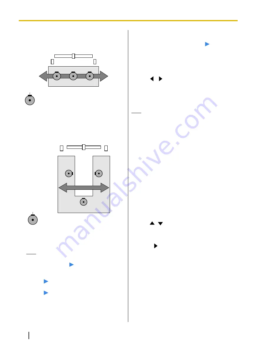
When setting Digital Boundary Microphones
parallel with the display:
Connector
Main video camera
Speaker
Speaker
Display
R ch
L ch
MIC 1
MIC 2
MIC 3
MIC 1:
"Right side"
MIC 2:
"Center Mono"
MIC 3:
"Left side"
When setting Digital Boundary Microphones as
follows:
Main video camera
R ch
L ch
MIC 2
MIC 3
MIC 1
Display
Speaker
Speaker
Connector
MIC 1:
"Right side"
MIC 2:
"Center Mono"
MIC 3:
"Left side"
Note
•
Make some noise near the Digital Boundary
Microphone.
"
"
is displayed to indicate
which Digital Boundary Microphone picks
up the noise.
•
"
"
is not displayed when the Digital
Boundary Microphone is mute.
•
"
"
is not displayed when multiple Digital
Boundary Microphones pick up the sound at
the same time.
•
When the Digital Boundary Microphone is
mute, the sound made by pressing the MIC
Mute button might make
"
"
appear.
8.
Press
[G]
.
•
A dialog box to confirm the saving of settings is
displayed.
9.
Use
[
][
]
to select
"Yes"
and press
[Enter]
.
•
The system settings screen is displayed.
10.
Press
[Home]
.
•
The Home screen is displayed.
Note
•
Do not move Digital Boundary Microphones
after completing settings. Otherwise the
settings will not match the location of the Digital
Boundary Microphone.
Making Remote Control
Settings
You can specify a remote control ID from 1, 2, or 3 for
both the remote control and the unit. The unit responds
to signals from any remote control with the same remote
control ID as itself. If you do not specify an ID, the unit
responds to signals from all remote controls. You can
confirm the remote control ID for the unit on the Home
screen (Page 31).
1.
Press
[Menu]
.
•
The Menu screen is displayed.
2.
Use
[
][
]
to select
"Settings"
and press
[Enter]
.
•
The system settings screen is displayed.
3.
Press
[
]
.
•
The second page is displayed.
96
Operating Manual
Document Version 2012-03
Contacts and Settings


