14
3
Device Installation
Note: All the installation and operations here should conform to your local electric safety rules.
3.1
Check Unpacked NVR
When you receive the NVR from the forwarding agent, please check whether there is any visible damage.
The protective materials used for the package of the NVR can protect most accidental clashes during
transportation. Then you can open the box to check the accessories.
Please check the items in accordance with the list. Finally you can remove the protective film of the NVR.
3.2
About Front Panel and Rear Panel
The model label in the front panel is very important; please check according to your purchase order.
The label in the rear panel is very important too. Usually we need you to represent the serial number
when we provide the service after sales.
3.3
HDD Installation
Important
:
Please turn off the power before you replace the HDD.
The pictures listed below for reference only.
For the first time install, please be aware that whether the HDDs have been installed.
You can refer to the Appendix for recommended HDD brand. Please use HDD of 7200rpm or higher.
Usually we do not recommend the PC HDD.
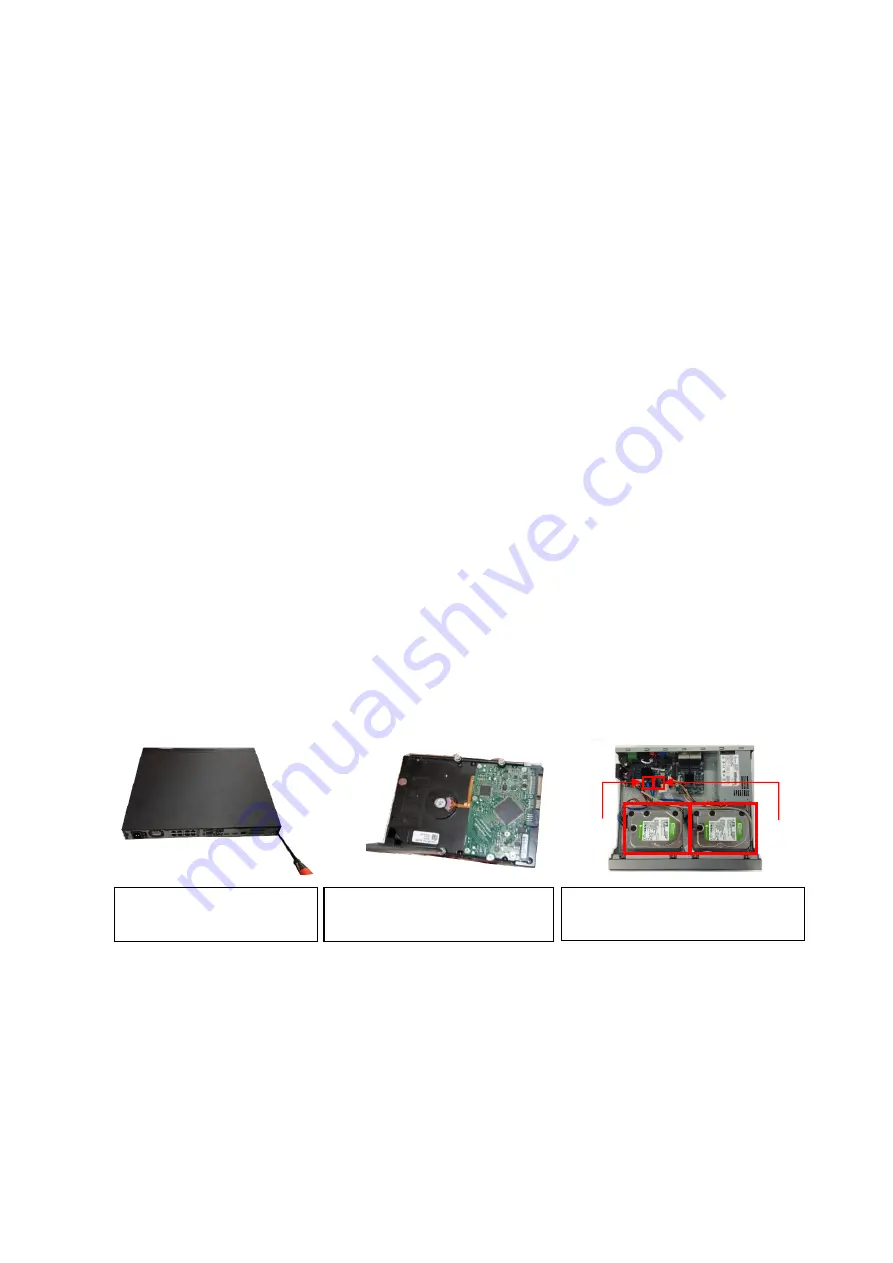
Please follow the instructions below to install hard disk.
1. Loosen the screws of the
upper cover and side panel.
2. Fix four screws in the HDD
(Turn just three rounds).
3.
Place the HDD in accordance with
the four holes in the bottom.
HDD2
HDD1
Содержание k-nl304g
Страница 1: ...Network Video Recorder User s Manual Model No K NL304K G K NL308K G Version 1 0 2 ...
Страница 41: ...33 Figure 4 24 Tips On the navigation bar click to enable disable tour Click Save button to save current setup ...
Страница 58: ...50 Figure 4 51 Figure 4 52 ...
Страница 78: ...70 Figure 4 70 Figure 4 71 ...
Страница 79: ...71 Figure 4 72 Figure 4 73 ...
Страница 86: ...78 Figure 4 80 Figure 4 81 ...
Страница 87: ...79 Figure 4 82 Figure 4 83 ...
Страница 90: ...82 Figure 4 86 Figure 4 87 4 11 Network 4 11 1 Basic Setup ...
Страница 113: ...105 Figure 4 110 In Figure 4 110 click one HDD item the S M A R T interface is shown as in Figure 4 111 Figure 4 111 ...
Страница 116: ...108 Figure 4 114 Figure 4 115 ...
Страница 127: ...119 Figure 4 128 Figure 4 129 ...
Страница 162: ...154 Figure 5 40 Figure 5 41 ...
Страница 163: ...155 Figure 5 42 Figure 5 43 Figure 5 44 ...
Страница 171: ...163 Figure 5 56 Figure 5 57 Figure 5 58 Figure 5 59 Please refer to the following sheet for detailed information ...
Страница 173: ...165 Figure 5 60 Figure 5 61 ...


