background image

© Panasonic Corporation 2012 Unauthorized copy-
ing and distribution is a violation of law.

ORDER NO. VM1202008CE

B27

Dual Camera

Model No.

HX-WA2P
HX-WA2PC
HX-WA2PU
HX-WA2EB
HX-WA2EC
HX-WA2EE
HX-WA2EF
HX-WA2EG
HX-WA2GA
HX-WA2GC
HX-WA2GD
HX-WA2GK
HX-WA2GN
HX-WA2GT

Colour
(D)...........Orange Type
(A)...........Blue Type (except GK)

Содержание HX-WA2EB

Страница 1: ...and distribution is a violation of law ORDER NO VM1202008CE B27 Dual Camera Model No HX WA2P HX WA2PC HX WA2PU HX WA2EB HX WA2EC HX WA2EE HX WA2EF HX WA2EG HX WA2GA HX WA2GC HX WA2GD HX WA2GK HX WA2GN HX WA2GT Colour D Orange Type A Blue Type except GK ...

Страница 2: ...and P C B 9 4 Specifications 10 5 Location of Controls and Components 13 6 Troubleshooting Guide 15 6 1 Confirmation Flow of Waterproof 15 6 2 Airtight Inspection with Air Leak Tester 16 6 3 Air Leak Tester RFKZ0528 Operating Instruction 17 7 Service Fixture Tools 21 7 1 When Replacing the Main P C B 21 7 2 Necessary Tool Jig 21 8 Disassembly and Assembly Instructions 22 8 1 Disassembly Flow Chart...

Страница 3: ...exposed to shock hazards 1 2 Leakage Current Cold Check 1 Unplug the AC cord and connect a jumper between the two prongs on the plug 2 Measure the resistance value with an ohmmeter between the jumpered AC plug and each exposed metal lic cabinet part on the equipment such as screwheads connectors control shafts etc When the exposed metal lic part has a return path to the chassis the reading should ...

Страница 4: ...ng Procedure 1 Refer to the disassemble procedure and Remove the necessary parts unit 2 Put the insulation tube onto the lead part of Resistor ERG5SJ102 1kΩ 5W an equivalent type of resistor may be used 3 Put the resistor between both terminals of capacitor on MAIN P C B for approx 5 seconds 4 After discharging confirm that the capacitor voltage is lower than 10V using a voltmeter Fig F1 ...

Страница 5: ...ly a grounded tip soldering iron to solder or unsolder ES devices 4 Use only an antistatic solder removal device Some solder removal devices not classified as antistatic ESD protected can generate electrical charge sufficient to damage ES devices 5 Do not use freon propelled chemicals These can generate electrical charges sufficient to damage ES devices 6 Do not remove a replacement ES device from...

Страница 6: ...OTE This Lithium battery is a critical component It must never be subjected to excessive heat or discharge It must therefore only be fitted in requirement designed specifically for its use Replacement batteries must be of same type and manufacture They must be fitted in the same manner and location as the original battery with the correct polarity contacts observed Do not attempt to re charge the ...

Страница 7: ...using the lead free solder To put lead free solder it should be well molten and mixed with the original lead free solder Remove the remaining lead free solder on the P C B cleanly for soldering of the new IC Since the melting point of the lead free solder is higher than that of the normal lead solder it takes the longer time to melt the lead free solder Use the soldering iron more than 70W equippe...

Страница 8: ...thods To define the model suffix to be serviced refer to the rating label and caution label which are putted on the Unit NOTE After replacing the MAIN P C B or IC121 be sure to achieve update the Firmware and adjustment 1 The firmware together with version up procedure are available at software download on the Support Information from NWBG VDBG AVC web site in TSN system 2 The adjustment instructi...

Страница 9: ...pid heating For that case please test the baking of IC and P C B before replacing IC in order to prevent the above mentioned problem IC Service parts and P C B should be put in the heater together Reference value for baking temperature and time is as follows Baking temperature and time Hour 80 C 12 hour Note This setting value of temperature and time Hour is actually used in Japan An appropriate s...

Страница 10: ...10 4 Specifications ...

Страница 11: ...11 ...

Страница 12: ...12 ...

Страница 13: ...s on the LCD monitor screen However this is not a malfunction and does not affect the recorded picture 1 2 8 3 7 6 4 5 9 Zoom range button 10 Photoshot button 11 SET button SET Use the SET button to select the recording functions and playback operations and to operate the menu screen 12 In Recording Mode Zoom button W T In Playback Mode Volume button Zoom button W T Thumbnail display switch 13 Rec...

Страница 14: ...uched Please do not touch the flash 21 Hand strap fixture Adjust the length after passing your arm through the hand strap 22 Speaker 23 Internal stereo microphones 24 Tripod receptacle If you attach a tripod which has a 5 5 mm 0 22 S screw or larger it may damage this unit 19 20 21 22 23 24 ...

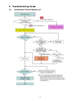
Страница 15: ...15 6 Troubleshooting Guide 6 1 Confirmation Flow of Waterproof ...

Страница 16: ...16 6 2 Airtight Inspection with Air Leak Tester ...

Страница 17: ...17 6 3 Air Leak Tester RFKZ0528 Operating Instruction ...

Страница 18: ...18 ...

Страница 19: ...19 ...

Страница 20: ...20 ...

Страница 21: ...stment 1 The firmware together with version up procedure are available at software download on the Support Information from NWBG VDBG AVC web site in TSN system 2 The adjustment instruction is available at software download on the Support Information from NWBG VDBG AVC web site in TSN system together with Maintenance software 7 2 Necessary Tool Jig ...

Страница 22: ...22 8 Disassembly and Assembly Instructions 8 1 Disassembly Flow Chart This is a disassembling chart When assembling perform this chart conversely ...

Страница 23: ...ews K 3 Solders Fig D16 Battery Case Earth Plate Main P C B 10 Lens Holder Fig D17 3 Screws L Lens Holder 11 Speaker Fig D18 1 Screw M Speaker Speaker Holder 12 LCD Unit Fig D19 2 Screws N 2 O Rings Fig D20 2 Screws O Side R Cover Side R Ornament Rear Ornament Fig D21 2 Screws P 2 O Rings Fig D22 LCD Unit Fig D23 NOTE When Installing 13 Hinge Cover LCD Case T Unit Fig D24 1 Screw Q Fig D25 Hinge C...

Страница 24: ...24 8 3 1 Removal of the Top Ornament Fig D1 8 3 2 Removal of the Front Cabinet Unit Fig D2 8 3 3 Removal of the Side L Cabinet Unit Fig D3 ...

Страница 25: ...25 Fig D4 Fig D5 ...

Страница 26: ...26 Fig D6 8 3 4 Removal of the Battery Cover Fig D7 Fig D8 8 3 5 Removal of the Waterproof Rubber Fig D9 ...

Страница 27: ...27 Fig D10 8 3 6 Removal of the Capacitor Capacitor Holder Fig D11 ...

Страница 28: ...28 8 3 7 Removal of the Lens Unit Fig D12 Fig D13 ...

Страница 29: ...29 8 3 8 Removal of the Flash Unit Fig D14 8 3 9 Removal of the Main P C B and Battery Case Fig D15 ...

Страница 30: ...30 Fig D16 8 3 10 Removal of the Lens Holder Fig D17 8 3 11 Removal of the Speaker Fig D18 ...

Страница 31: ...31 8 3 12 Removal of the LCD Unit Fig D19 Fig D20 ...

Страница 32: ...32 Fig D21 Fig D22 ...

Страница 33: ...33 Fig D23 8 3 13 Removal of the Hinge Cover LCD Case T Unit Fig D24 Fig D25 ...

Страница 34: ...34 Fig D26 Fig D27 8 3 14 Removal of the LCD O Ring Fig D28 ...

Страница 35: ...35 Fig D29 8 3 15 Removal of the LCD Panel Fig D30 ...

Страница 36: ...36 Fig D31 8 3 16 Removal of the Mic Unit Monitor P C B Fig D32 Fig D33 ...

Страница 37: ...37 Fig D34 8 3 17 Removal of the LCD Hinge Unit Fig D35 ...

Страница 38: ...38 Fig D36 Fig D37 ...

Страница 39: ...39 8 3 18 Removal of the Switch Unit Fig D38 Fig D39 ...

Страница 40: ... with PC Connection method of the main unit and an exclusive adjustment jig as follows 9 1 1 Adjustment Procedure Connect the main unit to PC with USB The adjustment instruction is available at Software download on the Support Information from NWBG VDBG AVC web site in TSN System Figure of connection Figure of image when adjustment Part Number of jig Only a necessary jig mentions it in setup of el...

Страница 41: ...stment item as follows The adjustment instruction is available at Software download on the Support Information from NWBG VDBG AVC web site in TSN System The firmware together with version up procedure are available at Software download on the Support Information from NWBG VDBG AVC web site in TSN System ...

Страница 42: ...42 10 Maintenance 10 1 Regular Maintenance Flow ...

Страница 43: ...43 10 2 Component Kits of Waterproof ...

Страница 44: ... 0 3 P SLVSD 0 3 N COMPOSITE VIDEO CN141 IC108 USB IF SW SD I F HALL SENSOR KEY MATRIX HPD DDC_ SCL SDA CEC TMDS_CLK TMDS_DATA0 TMDS_DATA1 TMDS_DATA2 ID USB_D IC501 SWITCHING CONTROL RTC X3001 32 768KHz BSRST I2C_ SDA SCL LCD I F SD CARD CN173 HINGE ADCK RESET_N TGVD CMOS_ SDA SCL AUDIO LINE OUT FPC EXCLKS GREEN_LED DB_ZOOM PLAY MENU IC303 HALL SENSOR PANEL_OPEN KEY_POW RED_LED IC521 USB CHARGE FL...

Страница 45: ... SD PANEL_OPEN I2C_ SCL SDA SP BSRST BACKUPBAT TO CN103 EXCLKS POWER SEQUENCER IC121 OneNAND ZFRD ZFWR D 0 15 ZCS0 SLVSCP SLVSCN SLVSD 0 3 P SLVSD 0 3 N CMOS_ SDA SCL RESET_N TGVD ADCK IC951 LENS DRIVER LENS_ SCLK EN SDATA LENS_SOUT SHUTTER STATE_ F Z CN951 LENS_12M IC303 HALL SENSOR SP RED_LED GREEN_LED PWA BLOCK USB CHARGE CONTROL USB_SUSPWR S3001 POWER SW STA BLOCK FLASH CONTROL IC103 IC104 DDR...

Страница 46: ... IMAGE SENSOR LENS BLOCK DIAGRAM HX WA2 LENS BLOCK DIAGRAM LENS_SDATA LENS_SCLK LENS_12M LENS_EN STATE_F STATE_Z LENS_SOUT ZOOM MOTOR FOCUS MOTOR IRIS ZOOM_A ND ZOOM_B ZOOM_B ZOOM_A FOCUS_A FOCUS_B FOCUS_B FOCUS_A ND VDD3 VDD3 OUT1A OUT3A OUT1B OUT2A OUT2B OUT4B OUT4A OUT3B OUT6B OUT5A OUT5B OUT6A PIOUT1 CSB STATE1 SCLK SDATA FCLK STATE2 IN6 IN5A SOUT DRIVE DRIVE 26 17 ZOOM_PI FOCUS_PI IC951 LENS ...

Страница 47: ..._SDA SCL I2C_SCL VIN8 VDD5 VDD5ON VIN5 VOUT5 CMOS1 8 IC502 IC505 REG VDD1 5 PVIN4 L5031 STEP DOWN CIRCUIT SW3 VDD1 1 L5041 STEP DOWN CIRCUIT SW4 VAA2 8 SYS 3 VOUT 1 CE 4 VIN 3 CE 1 VOUT TO DMA TO DMA TO BATTERY TO DMA XIN XOUT X3001 32 768KHz TO DMA FLASH BLOCK DIAGRAM HX WA2 FLASH BLOCK DIAGRAM CHG ZCHGDONE FLCTL AL3 2V 7 2 C5401 T5401 D5402 Q5402 POWER FILTER OSCILLATION TRANSFORMER BLOCK RECTIF...

Страница 48: ...A0 10 TMDS SHLD0 11 TMDS DATA0 12 TMDS CLK 13 TMDS CLK SHD 14 TMDS CLK 15 CEC 16 DDC CEC GND 17 DDC SCL 18 DDC SDA 19 DDC 5V Z1 Z2 Z3 Z4 CN141 1 DATA3 2 COMMAND 3A VSS 3B VSS 4A VDD 4B VDD 5 CLOCK 6 VSS 7 DATA0 8 DATA1 9 DATA2 10 CARD 11 COMMON 12 WP 13 GND 14 GND CN103 1 MIC_GND 2 MIC_R 3 MIC_GND 4 MIC_L 5 MIC_GND 6 MICBIAS 7 BACKUP_BAT 8 GND 9 LCD_AN 10 LCD_CA 11 GND 12 LCDSD 13 LCDCK 14 LCDEN 1...

Страница 49: ...Model No HX WA2 Schematic Diagram Note ...

Страница 50: ...Model No HX WA2 Parts List Note ...

Страница 51: ...Model No HX WA2 Main CAA Schematic Diagram Main P C B ...

Страница 52: ...Model No HX WA2 Main DMA Schematic Diagram Main P C B ...

Страница 53: ...Model No HX WA2 Main PWA Schematic Diagram Main P C B ...

Страница 54: ...Model No HX WA2 Main STA Schematic Diagram Main P C B ...

Страница 55: ...Model No HX WA2 Monitor Schematic Diagram Monitor P C B ...

Страница 56: ...Model No HX WA2 Main P C B Component Side ...

Страница 57: ...Model No HX WA2 Main P C B Foil Side ...

Страница 58: ...Model No HX WA2 Monitor P C B Component Side ...

Страница 59: ...Model No HX WA2 Monitor P C B Foil Side ...

Страница 60: ...C1071 F1G1A1040006 C CAPACITOR CH 10V 0 1U 1 C1072 F1G1A1040006 C CAPACITOR CH 10V 0 1U 1 C1073 F1G1A1040006 C CAPACITOR CH 10V 0 1U 1 C1074 F1G1A1040006 C CAPACITOR CH 10V 0 1U 1 C1075 F1G0J1050007 C CAPACITOR CH 6 3V 1U 1 C1076 F1G1A1040006 C CAPACITOR CH 10V 0 1U 1 C1078 F1G1A1040006 C CAPACITOR CH 10V 0 1U 1 C1079 F1G1A1040006 C CAPACITOR CH 10V 0 1U 1 C1080 F1G1A1040006 C CAPACITOR CH 10V 0 1...

Страница 61: ...ACITOR 1 C5022 F1J0J2260004 C CAPACITOR CH 6 3V 22U 1 C5031 F1J0J1060007 C CAPACITOR 1 C5032 F1J0J2260004 C CAPACITOR CH 6 3V 22U 1 C5033 F1J0J2260004 C CAPACITOR CH 6 3V 22U 1 C5042 F1J1A106A043 C CAPACITOR CH 10V 10U 1 C5043 F1G1H220A565 C CAPACITOR CH 50V 22P 1 C5061 F1J1A106A043 C CAPACITOR CH 10V 10U 1 C5068 F1G1E221A090 C CAPACITOR 1 C5072 F1H1C2250001 C CAPACITOR 1 C5082 F1G0J1050007 C CAPA...

Страница 62: ... F5009 K5H502Z00003 FUSE 1 IC101 C1AB00003893 IC 1 E S D IC103 C3ABTY000074 IC 1 E S D IC104 C3ABTY000074 IC 1 E S D IC108 C0ZBZ0001937 IC 1 E S D IC109 C0BBAA000103 IC 1 E S D IC121 VU4097164300 IC 1 E S D IC181 VU4107328401 IC 1 E S D IC303 VU4096949314 IC 1 E S D IC501 C1ZBZ0004584 IC 1 E S D IC502 VU4097101315 IC 1 E S D IC503 VU4097065617 IC 1 E S D IC505 VU4097101315 IC 1 E S D IC521 VU40971...

Страница 63: ...SISTOR 1 R1039 D0GA102JA042 RESISTOR 1 R1045 D0GA470JA042 RESISTOR 1 R1046 D0GA272ZA029 RESISTOR 1 R1047 D0GA272ZA029 RESISTOR 1 R1072 D0GA103ZA029 RESISTOR 1 R1073 D0GA103ZA029 RESISTOR 1 R1074 VU4012864417 RESISTOR 1 R1076 D0GA103ZA029 RESISTOR 1 R1077 D0GA103ZA029 RESISTOR 1 R1078 VU4012864417 RESISTOR 1 R1081 D0GAR00ZA031 RESISTOR 1 R1082 D0GAR00ZA031 RESISTOR 1 R1121 D0GA101JA042 RESISTOR 1 R...

Страница 64: ...GA182JA042 RESISTOR 1 R9001 D0GAR00ZA031 RESISTOR 1 R9002 D0GAR00ZA031 RESISTOR 1 R9003 D0GAR00ZA031 RESISTOR 1 R9004 D0GAR00ZA031 RESISTOR 1 R9005 D0GA222JA042 RESISTOR 1 R9006 D0GA432JA042 RESISTOR 1 R9008 D0GA103JA042 RESISTOR 1 R9013 D0GA472JA042 RESISTOR 1 R9014 D0GA472JA042 RESISTOR 1 R9501 D0GA2R2ZA032 RESISTOR 1 R9504 D0GA221JA042 RESISTOR 1 R9505 D0GA221JA042 RESISTOR 1 R9506 D0GA393JA042...

Страница 65: ...me Description Q ty Remarks S3003 VU6450452857 SWITCH 1 S3004 VU6450452857 SWITCH 1 T5401 G5ZZ00000137 TRANSFORMER 1 TH301 D4CCY104A004 THERMISTOR 1 X1102 H0J480500056 CRYSTAL OSCILLATOR 1 X3001 H0J327200255 CRYSTAL OSCILLATOR 1 Z6301 VU6450989551 BATTERY 1 ...

Страница 66: ...Model No HX WA2 Frame and Casing Section 1 ...

Страница 67: ...Model No HX WA2 Frame and Casing Section 2 ...

Страница 68: ...Model No HX WA2 Packing Parts and Accessories Section ...

Страница 69: ...ER 1 42 VU6361589901 HEAT SINK 1 43 VU6361591348 CABINET UNIT 1 D 43 VU6361591362 CABINET UNIT 1 A 44 VU6361517881 CAUTION LABEL 1 PC 45 VU6361517874 CAUTION LABEL 1 P PC PU EG EF EC EB GC GA EE GN 45 VU6361517898 CAUTION LABEL 1 GT 45 VU6361517904 CAUTION LABEL 1 GD 45 VU6361517911 CAUTION LABEL 1 GK D 46 VU6361395687 ANGLE 1 47 VU6361566131 SIDE R COVER 1 D 47 VU6361568241 SIDE R COVER 1 A 48 VU...

Страница 70: ... VU4120800700 SCREW 1 B15 VU4120800700 SCREW 1 B16 VU4120750609 SCREW 1 D B16 VU4120811706 SCREW 1 A B17 VU4120750609 SCREW 1 D B17 VU4120811706 SCREW 1 A B18 VU4120750609 SCREW 1 D B18 VU4120811706 SCREW 1 A B19 VU4120750609 SCREW 1 D B19 VU4120811706 SCREW 1 A B20 VU4120750609 SCREW 1 D B20 VU4120811706 SCREW 1 A B21 VU4111902208 SCREW 1 B22 VU4111902208 SCREW 1 B23 VU4112134202 SCREW 1 B24 VU41...

Страница 71: ... VSK0756 AC ADAPTOR 1 GK 305 VSK0755 AC ADAPTOR 1 GD 305 VSK0757 AC ADAPTOR 1 GT 306 VFA0555 AV CABLE 1 307 VFA0554 USB CABLE 1 308 VFF0905 C CD ROM 1 P PC PU GT GD EG EF EC EB GC GA EE GN 308 VFF0906 C CD ROM 1 GK 309 VFF1003 CD ROM O I 1 EG EF EC 309 VFF1004 CD ROM O I 1 GC GA EE GN 310 VQL2M26 BUTTON LABEL 1 PC 310 VQL2M27 BUTTON LABEL 1 GT 311 VFC4817 HANDSTRAP 1 312 VYC1013 BRUSH 1 313 VQT4F1...

Страница 72: ...X WA2 Parts List Safety Ref No Part No Part Name Description Q ty Remarks 313 VQT4F41 OPERATING INSTRUCTIONSS RUSSIAN UKRAINI AN 1 EE 313 VQT4F42 OPERATING INSTRUCTIONS CHINESE SIMPLIFI ED 1 GK 314 BATTERY PACK 1 ...

Отзывы: