21
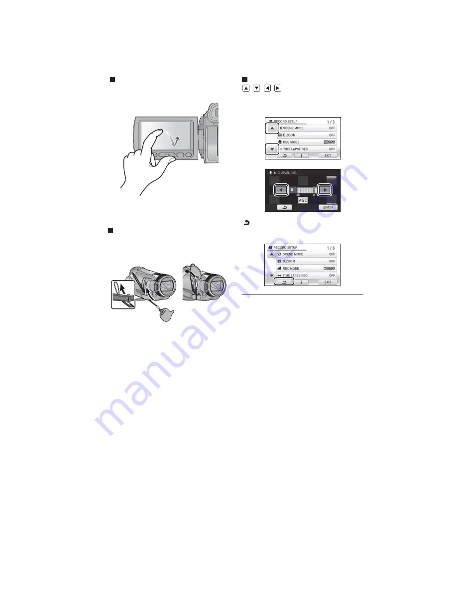
How to use the touch screen
You can operate by directly touching the LCD monitor (touch screen) with your finger.
It is easier to use the stylus pen (supplied) for detailed operation, or if it is hard to operate with your fingers.
Touch
Touch and release the touch screen to select
icon or picture.
●
Touch the center of the icon.
●
Touching the touch screen will not operate
while you are touching another part of the
touch screen.
About the Stylus pen
The stylus pen (supplied) can be stored on the
unit as shown when it is not being used. Remove
the stylus pen from the unit when it is to be used.
●
Only use the supplied stylus pen.
●
Do not tuck the stylus pen with the LCD
monitor.
About the operation icons
/
/
/
:
These icons are used to switch between the
menu and thumbnail display page, for item
selection and setting etc.
:
Touch to return to the previous screen such
as when setting menus
●
Wipe the LCD monitor with a soft cloth, such
as eye glass cleaner, when it gets dirty with
finger prints etc.
●
Do not touch on the LCD monitor with hard
pointed tips, such as ball point pens.
●
Do not touch the LCD monitor with your finger
nails, or rub or press with strong force.
●
It may become hard to see or hard to
recognize the touch when the LCD protection
sheet is affixed.
●
Perform the touch screen calibration when the
touch is not recognized or wrong location is
recognized.
Содержание HDC-HS300EB
Страница 11: ...11 3 5 2 Precautions for installing HDD ...
Страница 14: ...14 4 Specifications ...
Страница 15: ...15 ...
Страница 16: ...16 ...
Страница 29: ...29 7 Disassembly and Assembly Instructions 7 1 Disassembly Flow Chart 7 2 PCB Location ...
Страница 32: ...32 7 3 2 Removal of the Side Case R Unit Fig D2 Fig D3 7 3 3 Removal of the Side Case L Unit Fig D4 ...
Страница 33: ...33 7 3 4 Removal of the HDD Unit Fig D5 7 3 5 Removal of the Top Case Unit Fig D6 ...
Страница 35: ...35 Fig D11 7 3 8 Removal of the Lens Unit Fig D12 Fig D13 7 3 9 Removal of the Main P C B Fig D14 ...
Страница 36: ...36 7 3 10 Removal of the Sub P C B Fig D15 7 3 11 Removal of the Side R P C B and Cooling Fan Motor Fig D16 ...
Страница 38: ...38 Fig D20 7 3 15 Removal of the Monitor P C B Fig D21 Fig D22 ...
Страница 39: ...39 7 3 16 Removal of the LCD Fig D23 7 3 17 Removal of the Front P C B Fig D24 ...
Страница 40: ...40 7 3 18 Removal of the Camera Operation Unit Fig D25 7 3 19 Removal of the Barrier Motor Unit Fig D26 ...
Страница 41: ...41 Fig D27 7 3 20 Removal of the Barrier Unit and MF Ring Ornament Fig D28 ...
Страница 42: ...42 7 3 21 Removal of the Flash Unit Fig D29 7 3 22 Removal of the ECM Fig D30 Fig D31 ...
Страница 44: ...44 7 3 26 Removal of the Speaker Fig D35 7 3 27 Removal of the Shoe Angle and Grip Ornament Fig D36 ...
Страница 45: ...45 Fig D37 7 3 28 Removal of the MOS Unit and Optical Filter Fig D38 7 3 29 Removal of the Zoom Motor Fig D39 ...
Страница 84: ...S 33 S4 12 EVF FPC P C B 6 0 0 5 6 Foil Side HDC HS300 Series EVF FPC P C B 10 9 8 7 6 5 4 3 2 1 G F E D C B A ...
Страница 88: ...S 37 S4 15 Front FPC P C B 6 6 HDC HS300 Series Front FPC P C B 10 9 8 7 6 5 4 3 2 1 G F E D C B A Foil Side ...
Страница 89: ...S 38 ...
Страница 102: ...S6 3 EVF Section S 51 B45 55 B44 52 56 57 58 59 53 54 43 44 47 46 48 49 50 51 45 60 62 61 B46 ...
Страница 103: ...S6 4 LCD Section S 52 161 162 163 157 158 B151 B152 151 159 156 155 145 160 164 153 B153 B154 152 154 ...


