
5
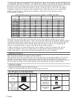
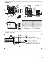
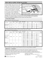
DIMENSIONS
WIRING
DIAGRAM
Multi-Speed module (FV-0511VKS2
only, other models not included)
Plug ‘N Play module slot
Plug ‘N Play module slot
Power switch
Signal switch
Fan body
DC-Motor
Junction box
Unit: inches (mm)
FV-1115VK2
FV-0511VKS2
FV-1115VK2
10 1/4 (260)
5 7/8 (151)
5 7/8 (148)
13 (330)
7 1/2 (190)
1 1/4 (30)
4 1/2 (114)
1 1/2 (37)
3 7/8 (100)
12 (304)
3 3/8 (86)
13 1/4 ~ 15 1/2 (336~394) 16 1/2 ~ 18 3/4 (419~480) 21 1/4 ~ 23 1/2 (540~597)
3 3/8 (86)
6 5/8 (169)
10 1/4 (261)
13 (330)
3 7/8
(100)
3 7/8
(100)
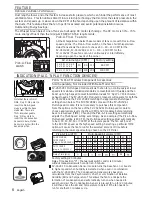
1
8
3
4
2
FV-0511VK2
FV-1115VK2
Part name
Blade
Grille
Part name
No.
No.
8
2
4
1
3
5
6
10
12
11
Motion sensor location
(FV-MSVK1 not included)
Multi-Speed module
(FV-0511VKS2 only,
other models not included)
Connector cover
Base PCB box
Pick-A-Flow switch
Fan
body
Damper
TM
Flex-Z Fast
bracket
Junction box
9
7
6
Adaptor
7
9
7
10
11
12
13
Main PCB box
13
5
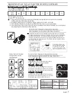
English
Black
White
Red
Red
Green
Earth ground
Live (Fan)
Neutral
AC120V
60Hz
(Power supply)
Green
Use signal switch for manual control of High/Low CFM modes
On to use Pick-A-Flow setting ( High CFM )
Do not connect the red signal wires to a live power
supply (AC 120V 60 Hz), it will damage the product.
Please use an optional switch to connect the red
signal wires.
OFF to use multi-speed module setting ( Low CFM )