Panasonic FV-0511VK2 Скачать руководство пользователя страница 2

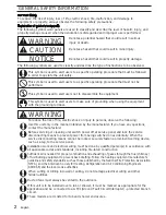
To reduce  the risk of injury, loss of life, electric shock, fire, malfunction, and damage to 

equipment or property, always observe the following safety precautions.

Denotes a potential hazard that could result in serious
injury or death.

Denotes a hazard that could result in minor injury.

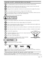
The following symbols are used to classify and describe the type of instructions to be observed.

This symbol is used to alert users to a specific operating procedure that must not be

performed.

This symbol is used to alert users to a specific operating procedure that must be followed

in order to operate the unit safely.

WARNING

WARNING

The following symbol word panels are used to classify and describe the level of hazard, injury, and

property damage caused when the denotation is disregarded and improper use is performed.

CAUTION

This symbol is used to alert users not to disassemble the equipment.

This symbol is used to alert users to make sure of grounding when using the equipment

with the grounding terminal.

GENERAL SAFETY INFORMATION

Denotes a hazard that could result in property damage.

To reduce the risk of fire, electric shock or injury to persons, observe the following :
Use this unit only in the manner intended by the manufacturer. If you have any questions,

contact the manufacturer. 
Before servicing or cleaning unit, switch power off at service panel and lock the service 

disconnecting means to prevent power from being switched on accidentally. When the 

service disconnecting means cannot be locked, securely fasten a prominent warning device, 

such as a tag, to the service panel.

Installation work and electrical wiring must be done by qualified person(s) in accordance with 

all applicable codes and standards, including fire-rated construction.
Sufficient air is needed for proper combustion and exhausting of gases through the flue (chimney)

of fuel burning equipment to prevent back drafting. Follow the heating equipment manufacturer’s

guideline and safety standards such as those published by the National Fire Protection Association

(NFPA), and the American Society for Heating, Refrigeration and Air Conditioning Engineers

(ASHRAE) and the local code authorities.

When cutting or drilling into wall or ceiling, do not damage electrical wiring and other 

hidden utilities.

Ducted fans must always be vented to the outdoors.

If this unit is to be installed over a tub or shower, it must be marked as appropriate for the 

application and be connected to a GFCI (Ground Fault Circuit Interrupter) - protected branch 

circuit.

These models are UL listed for tub and shower enclosures.

2

NOTICE


For Your Safety

Explanation of symbol word panels
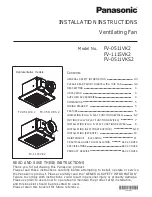
English

Содержание FV-0511VK2

Страница 1: ...V 0511VKS2 FV 0511VK2 FV 1115VK2 Representative models 2 3 3 4 4 4 4 5 5 5 6 7 7 8 8 10 10 11 BACK COVER BACK COVER PRACTICAL GUIDE TO INSTALLATION BACK COVER READ AND SAVE THESE INSTRUCTIONS Thank you for purchasing this Panasonic product Please read these instructions carefully before attempting to install operate or service the Panasonic product Please carefully read the GENERAL SAFETY INFORMAT...

Страница 2: ...e manufacturer If you have any questions contact the manufacturer Before servicing or cleaning unit switch power off at service panel and lock the service disconnecting means to prevent power from being switched on accidentally When the service disconnecting means cannot be locked securely fasten a prominent warning device such as a tag to the service panel Installation work and electrical wiring ...

Страница 3: ...e speed control device Solid state controls may cause harmonic distortion which can cause motor humming noise Follow all local electrical and safety codes as well as the National Electrical Code NEC and the Occupation Safety and Health Act OSHA Always disconnect the power source before working on or near the fan motor or junction box Protect the supply wiring from sharp edges oil grease hot surfac...

Страница 4: ...are listed by UL under UL file No E78414 These products use a sirocco fan driven by a DC motor powered by an integral transformer The motor is designed to have long operating life high dynamic response higher speed ranges with saving energy The grille covering the fan body is a spring loaded quick remove type A damper for preventing air counter flow is provided The blower uses a high capacity siro...

Страница 5: ...e Blade Grille Part name No No 8 2 4 1 3 5 6 10 12 11 Motion sensor location FV MSVK1 not included Multi Speed module FV 0511VKS2 only other models not included Connector cover Base PCB box Pick A Flow switch Fan body Damper TM Flex Z Fast bracket Junction box 9 7 6 Adaptor 7 9 7 10 11 12 13 Main PCB box 13 5 English Black White Red Red Green Earth ground Live Fan Neutral AC120V 60Hz Power supply ...

Страница 6: ...e selected amount of time before returning to the lower speed setting chosen on the CFM dial Pick A Flow CFM Multi Speed Air volume CFM 50 110 110 130 150 0 0 0 0 0 0 40 40 40 60 60 60 40 60 60 80 80 80 40 70 80 100 100 100 40 70 80 100 100 110 120 30 30 30 50 50 50 40 50 50 70 70 70 40 70 70 90 90 90 40 70 90 100 110 110 Factory setting 20 minutes Delay Time position 0 Manual wall switch control ...

Страница 7: ...FV VS15VK1 Fan Hi Low speed Depend on FV VS15VK1 Time delay setting FV MSVK1 FV VS15VK1 FV MSVK1 Motion Sensor module turns the base fan on or boosts to higher speed when motion is detected when using in combination with the FV VS15VK1 The Motion Sensor is pre set to run for 20 minutes it will then re check for movement if detected the fan will run for another 20 minutes cycle The Motion Sensor de...

Страница 8: ...ast bracket to joists by drilling 2 tapping screws which have been fixed on it Fig 2 TM TM 3 Adjust the length of Flex Z Fast bracket as the spacing between joists and install to joists by drilling the other 2 tapping screws which have been fixed on it Fig 3 4 Remove junction box cover and secure conduit or stress relief to junction box knock out hole Fig 4 TM 6 Install the adaptor to Flex Z Fast ...

Страница 9: ...k or other sealant to prevent air leakage 10 1 2 270 1 0 1 2 2 7 0 Ceiling Secure machine screw M4X8 to the suitable hole and not touch the Flex Z Fast bracket Please fix the screw carefully to avoid screw slip teeth TM 9 Finish ceiling work Ceiling hole should be aligned with the inside edge of the flange Fig 7 CAUTION CAUTION The claw of connector must latch the rib completely IMPORTANT Replace ...

Страница 10: ... working on unit 5 Follow the step 10 to 12 on INSTALLATION NEW CONSTRUCTION TM TM 3 Install the adaptor to Flex Z Fast bracket by using 2 self drilling screws Fig 12 4 Secure the fan body to Flex Z Fast bracket by using 2 self drilling screws plug connector to receptacle and secure the fan body to adaptor by using machine screw M4X8 Fig 13 Secure machine screw M4X8 to the suitable hole and not to...

Страница 11: ...er Use non abrasive kitchen detergent wipe dry with clean cloth Fig 16 3 The grille should be dry after cleaning 4 Remove dust and dirt from fan body using a vacuum cleaner Fig 17 5 Using a cloth dampened with kitchen detergent remove any dirt from fan body Wipe dry with clean cloth Fig 18 6 Reinstall grille 1 Remove grille by pulling down one mounting spring Fig 14 then pull down the other Pull d...

Страница 12: ...absorbs sound Clamps plus mastic or approved foil faced tape at all flex joints Foil tape tightly covers all metal duct joints glue PVC joints Properly insulate the area around the fan to minimize building heat loss and gain Fig 19 Loose fill or batt insulation can be placed directly over the fan housing in the attic Our fans does not create excessive heat that is a common problem with recessed li...

Отзывы: