39
2.3. Installation work of wireless unit
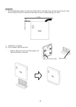
Refer to "1.2 Appearance/Dimensions" for the size of the wireless unit and the mounter.
1.
Wall mounting
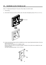
(1) Fixing of the mounter
Fix the mounter after making sure that the installation place has an
enough strength and flat surface of concrete, metal, wood, mortar,
etc.
• Fasten a screw (x1) temporarily on the installation surface.
• Make sure that the mounter can be installed in parallel, and then
fix it firmly with 2 screws located at the upper and the lower sides.
(Recommended tightening torque: 0.85 N
・
m ± 0.12 N
・
m)
Note
Use a screw whose nominal diameter is 4mm to fix
on the installation surface.
This screw shall be prepared by the installer
according to the material of the installation surface.
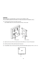
(2) Installation of the wireless unit
Fix the main unit onto the mounter fixed on
the wall.
• Hook the claws (x4) of the wireless unit
into the hook holes on the mounter.
• Align the side of the mounter and the dent in the wiring groove of
the wireless unit.
(3) Slide the wireless unit downward until the "click" sound is heard.
• To remove the wireless unit from the mounter, slide the wireless
unit upward while holding down the lever to the wall side.
(1)
(2)
Claw (x4)
Hook hole (x4)
Lever
Содержание EA-7HW02AP1
Страница 18: ...18 Mounter Outline view Unit mm 24 1 0 84 1 5 4 3 0 5 131 2 5 8 1 0 131 2 5 ...
Страница 19: ...19 Stand Outline view 56 2 1 5 122 2 5 66 9 1 5 ...
Страница 20: ...20 AC adapter Outline view Unit mm 95 9 1 5 28 5 1 0 43 8 1 5 ...
Страница 21: ...21 EA 7HW03AP1 Main unit Outline view Unit mm 38 5 1 5 201 7 2 5 201 7 2 5 ...
Страница 22: ...22 Mounter Outline view Unit mm 26 8 1 0 135 2 5 172 5 2 5 117 5 1 5 6 0 5 11 5 1 0 116 2 1 5 ...
Страница 23: ...23 AC adapter Outline view Unit mm Power cord Outline view 1200 150 50 109 1 5 34 1 5 48 1 5 1000 35 ...
Страница 55: ...55 Chapter 4 Setting method ...
Страница 61: ...61 Chapter 5 Response to error occurrence ...


