


ー
156
ー
Installation Instructions
Communication adaptor
3
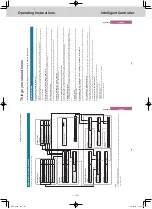
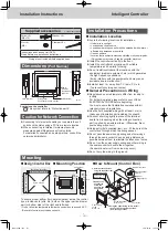
Basic wiring diagram
(Example using an Intelligent Controller )
Wire up the Communication Adaptor control wire and Inter-unit control wiring as shown in the
figure below.
Wiring procedure
Inter-unit control wiring
Communication Adaptor control wire
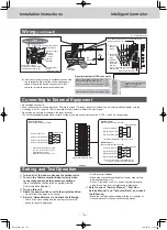
Precautions for the Communication Adaptor control wire
(Some items are duplicated in other sections.)
(1)The overall length should be 1 km or less.
(2)The communication wire has polarity. Connect so the positive and negative elements are
correct.
(3)Use only shielded wire. Be sure to ground only one end of the shielding.
10
11
12
ADAPT
(RS485)
10
11
12
ADAPT
(RS485)
10
11
12
ADAPT
(RS485)
10
11
12
ADAPT
(RS485)
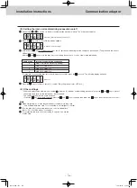
(4)Be sure to use crossover wiring, not a branching configuration.
* Connect the Intelligent Controller to the end of the crossover configuration.
0
1
2
3
10
11
12
13
CN32
B
A
S1
CN1
100-240V~
B
A
B
A
Communication
Adaptor 1
Communication
Adaptor 2
Communication
Adaptor 3
Communication
Adaptor 4
3
Terminating resistance
plug for Communication
Adaptor control wire
Terminating resistance
“off” (factory setting)
Terminating
resistance “on”
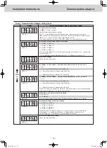
(6)Do not hook more than 16 units up
to the Communication Adaptor. The
system you are using (such as an
Intelligent Controller) may have
further restrictions. Consult the
installation manual for your system.
* The Intelligent Controller has a
maximum restriction of seven
units.
(7)Make sure that high voltage (ex. 230
V) AC lines are not connected to the
Communication Adaptor control wire
or the inter-unit control wiring terminals.
* If high voltage AC is accidentally
applied to the inter-unit control
wiring terminals, a fuse will blow
to protect the controller board.
If this happens, disconnect the AC
line, and connect the U2 terminal
wire of the inter-unit control wiring
to the spare terminal. (Do not
change the U1 terminal wire.)
Spare terminals are located right
next to U2.
Change terminal number 1 LINK1-
U2
o
to terminal number 2 (LINK1-
U2)
Change terminal number 4 LINK2-
U2
o
to terminal number 5 (LINK2-
U2)
Intelligent
Controller
Communication
Adaptor
Intelligent
Controller
Communication
Adaptor
G
W
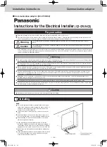
Intelligent controller
Inter-unit control wiring
Communication
Adaptor control
wire
Communication
Adaptor
Communication
Adaptor
G: Gas flow meter
W: Power flow meter
Inter-unit control wiring
Use the shielded wire for inter-unit
control wiring.
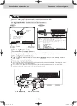
Connect terminals 0 and 1 (LINK1) on
the Communication Adaptor signal
terminal strip CN2 to the inter-unit
control wiring terminals of the indoor
or outdoor unit. There is no polarity.
If connecting two inter-unit control
wiring systems, connect terminals 3
and 4 (LINK2) on CN2 in the same
manner.
Connect terminals 11 and 12 (ADAPT
+ and -) on the Communication
Adaptor signal line terminal strip CN2
with the same terminals on the other
Communication Adaptor.
The
terminals have polarity.
Connect so
the positive and negative elements are
correct.
When connecting,
be sure to use
crossover wiring, not a branching
configuration.
Outdoor unit
Outdoor unit
Outdoor unit
Indoor unit
Indoor unit
(5)Change the terminating resistance plug CN32 to the “B” side (with terminal resistance) on
the board for the Communication Adaptors at the terminal end of the configuration.
TGR-318_ENG.indb 156
2017/04/06 10:44:43