


ー
152
ー
Installation Instructions
Intelligent Controller
4
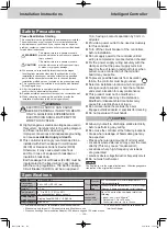
Power Supply Wiring
• Be sure to use a dedicated line for power source.
• Be sure to earth this controller.
• Do not connect the earth wiring to those of gas pipe, water
pipe, lighting rod, telephone, etc.
z
Type of wiring
•
Use a flexible wiring of 2 mm
2
(Recommended).
• Use the standard power supply wiring for Europe (such as
H05RN-F or H07RN-F which conform to CENELEC (HAR)
rating specifications) or use the wiring based on IEC
standard (60245 IEC57, 60245 IEC66).
z
Total Wire Length :
30 m or less
Inter-Unit Control Wiring
z
Type of wiring
•
Use a flexible shield wiring of 0.5 to 2 mm
2
.
• No polarity
z
Total Wire Length :
1000 m or less
z
Number of connectable units and devices :
(→ P.2 “Specifications”)
Communication Adaptor Control Wiring
(When connecting a Communication Adaptor)
z
Polarity (
+
/
-
) present
z
Number of connectable Communication Adaptor: up to 7 units
z
For the type of wiring and total wiring length,
see “Installation Instructions” supplied with the
Communication Adaptor.
External I/O Wiring
(When connecting external equipment)
z
Type of wiring
•
Use a flexible wiring of 0.5 to 2 mm
2
.
z
Wire Length :
20 m or less
Attention
• When using the controller at a location susceptible to noise,
use a shield wiring.
LAN Cable
(When connecting to a network)
z
Type of wiring
• Category 5 or above straight cable
z
Wire Length :
100 m or less
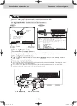
Preparations for Wiring
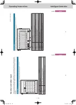
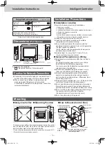
Basic Wiring Diagram
U1 U2
U1
U2
+
–
N
U1 U2
U1 U2
L
N
U1 U2
U1 U2
+
–
L
Power source (100-240 V~ 50/60 Hz)
Outdoor unit
This unit
Power supply
wiring
Communication
Adaptor
Communication
Adaptor
control wiring
• Polarity
present
Inter-unit control
wiring
• No polarity
Outdoor
unit
Indoor unit
Indoor unit
1-1
Indoor unit
1-2
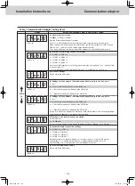
1. Turn the circuit breaker off before connecting the wiring
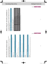
2. How to Attach the Ring Pressure Terminal
z
For power supply wiring
Process the end of each wiring, and
attach the ring pressure terminal (field
supplied item).
z
For shield wiring
Process the end of the each wiring and attach the ring
pressure terminal (field supplied item).
Remove wiring coat.
Shield mesh
Cover with the tape.
Strip
Shield mesh
Insulation tape
Attach ring pressure
terminal.
Ring pressure
terminal
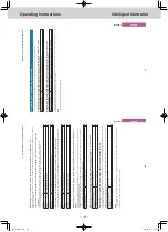
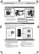
3. Remove the
power switch
cover
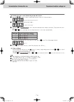
4. Wiring
Connect the power supply wiring.
z
Connect the power supply wiring and the earth wiring to
the power supply terminal board and the earth terminal
board
*3
(on the sheet metal case) respectively.
*3: Use earth terminal board as protective earth
• Do not over-tighten. (The screw may be damaged.)
Connect the inter-unit control wiring.
z
Connect the shield part of the shield wiring to No. 0 (FG
*4
)
of the signal terminal board (TB2).
*4: Functional Ground
• Do not over-tighten. (The screw may be damaged.)
z
There is no polarity.
Connect the Communication Adaptor control wiring.
z
Make sure the polarities (+/-) are correct.
Attention
• Read the “Installation Instructions” supplied with the
Communication Adaptor.
Connecting external equipment.
Attention
• See “Connecting to External Equipment” (P.5).
Fix the power supply wiring and other communication
wirings with the clamper (supplied) securely.
(Do not apply tensile force on the terminal connection part.)
Connect the LAN cable.
After all wiring arrangements are complete, turn
the circuit breaker on.
• Before power on, measure the voltage of the power supply
terminal board, and check it for the specified voltage.
Turning the power on with a voltage other than the
specified one may blow the fuse. If this occurs, no power
is supplied, and this unit may need to be replaced.
Strip
Ring
pressure
terminal
Screw
Screw
Power switch cover
Power-in port
Wiring
Attention
• Ground the shield on both sides of shield wiring, otherwise an
operation error from noise may occur.
shield wiring
Ground
Ground
TGR-318_ENG.indb 152
2017/04/06 10:44:41