


ー
140
ー
Operating Instructions
Intelligent Controller
188
Appendix
Appendix
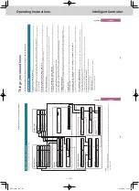
Number and letter input
This section explains the keyboard that is displayed on the screen that enables input of numbers and text. A
touchscreen numeric keypad is displayed for number input and a touchscreen keyboard is displayed for
text input.
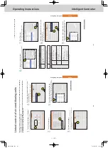
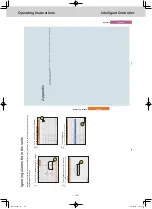
Number input
Use the touchscreen numeric keypad that is displayed on the screen when entering numbers such as times and temperatures. A touchscreen numeric keypad such as the following appears on the screen when you touch the text box.
1
2
3
4
5
Name
Explanation
1
Input field
The number you touch appears.
2
[DEL] key
This deletes all of the numbers displayed in the input field.
3
Numbered keys (0 to 9) [.] (dot) key [±] key
Touch the number
.
The number you touch is displayed in the input field and are add
ed to the right.
Each time you touch the [±] key
, a “-” (minus sign) is displayed or cleared.
4
[Cancel] key
The touchscreen numeric keypad closes when you touch this.
5
[Register] key
The numbers displayed in the input field are displayed as the se
tting values in the text box.
189
Appendix
Appendix
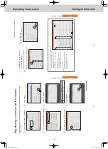
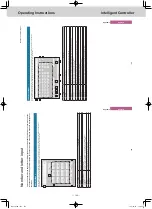
Character input
Use the touchscreen keyboard that is displayed on the screen when entering text such as when changing names and passwords. A touchscreen keyboard such as the following appears on the screen when you touch the text box.
1
2
5
6
6
5
3
4
7
9
10
11
12
8
Name
Explanation
1
Input field
The letter you touch appears.
2
Letter keys
Touch the letter
.
The letter you touch is displayed in the input field and is adde
d to the right.
3
[BS] key
Each time you touch it, the characters displayed are deleted one at a time from the left of the cursor
.
4
[DEL] key
Each time you touch it, the characters displayed are deleted one at a time from the right of the cursor
.
5
[<<][>>] keys
Touch [<<] to move the cursor to the beginning of the text. Touch [>>] to move the cursor to the end of the text.
6
[<][>] (move cursor) keys
Each time you touch one of these, the cursor in the input field
moves one character left or right.
7
[Space] key
Each time to touch this key
, 1
space is added to the input field.
8
[Uppercase] key
The keyboard layout is changed to capitals.
9
[Cancel] key
The touchscreen keyboard closes when you touch this.
10
[Copy] key
Copy the text in the input field you selected by dragging.
11
[Paste] key
Paste the text you copied with the [Copy] key in the cursor po
sition in the input field.
12
[Register] key
The text displayed in the input field is displayed as the settin
g text in the text box.
Number and letter input
TGR-318_ENG.indb 140
2017/04/06 10:44:36