background image

4

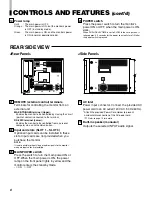
Tally lamp

Lights when the tally control signal is ON.

• Set the MAKE/TRIGGER terminal’s tally control in the

REMOTE (external control) terminal setup menu.

The lamp color can be set to red or green.

• To set the color, use TALLY SELECT in the “FUNCTION

SETTING” setup menu or MAKE/TRIGGER in the
REMOTE (external control) terminal setup menu.

For details, refer to pages 17 and 21.

PHASE adjustment knob

Adjusts picture hue.

• Turn the knob to the left to make the picture redder, and

turn it to the right to make the picture greener.

CHROMA adjustment knob

Adjusts picture color density.

• Turn the knob to the left to make the picture color lighter,

and turn it to the right to make the picture color deeper.

BRIGHT adjustment knob

Adjusts picture brightness.

• Turn the knob to the left to make the picture darker, and

turn it to the right to make the picture brighter.

CONTRAST adjustment knob

Adjusts picture contrast.

• Turn the knob to the left to make the picture contrast lower,

and turn it to the right to make the picture contrast higher.

VOLUME buttons

Adjusts the speaker volume.

• Pressing this button displays the VOLUME level bar on

the screen. Pressing the button again allows you to adjust
speaker volume.

MUTING button

Pressing this button mutes the output sound.

• To cancel “MUTING ON” (no sound), press MUTING

button again, or press the VOLUME “–” or “+” buttons.

NOTE:

When a menu or setting item (such as MAIN MENU, SET-UP
MENU, sub-menu, or VOLUME bar) is displayed on the screen,
this button functions as a control button for the menu screen. In
this case, it will not mute the sound when pressed.

VOLUME

SLOT 1

A

B

DEGAUSS

MENU

SCREENS

CHECK

ASPECT

AREA

MARKER

UNDER

SCAN

PULSE

CROSS

COLOR

OFF

SLOT 2

C

D

SLOT 3

POWER

E

F

INPUT SELECT

2

3

4

5

8

11 12 13 14

10

9

6

6

15 16 17

18

19 20

MUTING

7

VOLUME

SLOT 1

A

B

DEGAUSS

MENU

BLUE

CHECK

ASPECT

AREA

MARKER

UNDER

SCAN

PULSE

CROSS

COLOR

OFF

SLOT 2

C

D

SLOT 3

POWER

E

F

INPUT SELECT

1

CONTROLS AND FEATURES

FRONT VIEW

<Front Panel>

1

8

9

EMBEDDED AUDIO channel switch button

Press this button while the VOLUME bar is displayed
on the screen to change the input sound channel.

• When the 

 button is pressed, the next highest channel

is selected.

• When the 

 button is pressed, the next lowest channel is

selected.

NOTES:

Switchable channels correspond with the group selected in the
“E.AUDIO GROUP” of the “FUNCTION SETTING” setup menu.
* Valid when an input card compliant with EMBEDDED AUDIO is

installed.

Menu select buttons

Selects menu screen items or set-up menu screen.

MENU button

Displays, adjusts or closes a menu screen.

DEGAUSS button/lamp

Press the DEGAUSS button. The button lights
and degaussing is performed automatically.

• When the degaussing is completed, the light goes off.

UNDER SCAN button/lamp

Press the UNDER SCAN button. The button
lights and the screen is reduced (under-scan)
and the whole screen is displayed.

• When the UNDER SCAN button is pressed while lit, the light

goes off and the screen returns to normal size (over-scan).

• Use this function to check the whole screen.

NOTE:

This function is invalid with the RGB-input screen.

PULSE CROSS button/lamp

When you press the PULSE CROSS button, the
button lights and the picture moves horizontally
and vertically. The synchronized signal is
displayed and the screen automatically
brightens to make it easier to confirm the
synchronized sections.

• When the PULSE CROSS button is pressed while lit, the

light goes off and the normal screen is restored.

NOTE:

This function is invalid with the RGB-input screen.

2

3

4

5

6

12

13

7

10

11

LCT1464-001A_EN_02-09-6

03.9.19, 14:45

4

Содержание BTH1700BP - IND. MONITOR

Страница 1: ...r adjust this product please read these instructions completely Multi Format Monitor P LCT1464 001B 1003 MK MW VP Printed in Japan VQT0G67 1 VOLUME SLOT1 A B DEGAUSS MENU BLUE CHECK ASPECT AREA MARKER UNDER SCAN PULSE CROSS COLOR OFF SLOT2 C D SLOT3 POWER E F INPUT SELECT MUTING ...

Страница 2: ...als may be regulated in your community due to environmental considerations For disposal or recycling information please contact your local authorities or the Electronics Industries Alliance http www eiae org SAFETY PRECAUTIONS 䡵 HANDLING Avoid shocks or vibrations These may damage the unit and cause it to malfunction Do not block the ventilation slots Do not expose this unit to high temperatures E...

Страница 3: ...ROLS AND FEATURES INPUT CARD OPTIONAL 7 PREPARATION 9 BASIC MENU OPERATIONS MAIN MENU SET UP MENU 11 HOW TO USE MAIN MENU 13 HOW TO USE SET UP MENU 16 HOW TO USE EXTERNAL CONTROL 21 TROUBLESHOOTING 23 SELF CHECK INDICATIONS 25 SPECIFICATIONS 26 CONTENTS ...

Страница 4: ...AN PULSE CROSS COLOR OFF SLOT2 C D SLOT3 POWER E F INPUT SELECT 2 3 4 5 8 11 12 13 14 10 9 6 6 15 16 17 18 19 20 MUTING 7 VOLUME SLOT1 A B DEGAUSS MENU BLUE CHECK ASPECT AREA MARKER UNDER SCAN PULSE CROSS COLOR OFF SLOT2 C D SLOT3 POWER E F INPUT SELECT 1 CONTROLS AND FEATURES FRONT VIEW Front Panel 1 8 9 EMBEDDED AUDIO channel switch button Press this button while theVOLUME bar is displayed on th...

Страница 5: ...o AREA MARKER on page 14 for details This button does not operate when RGB is input The ZOOM function does not operate in the under scan mode 17 18 INPUT SELECT button lamp Selects an input signal from one of the input cards installed in the monitor s card slots SLOT1 SLOT3 Select SLOT1 press A or B Select SLOT2 press C or D Select SLOT3 press E or F Refer to the input card instructions on pages 7...

Страница 6: ... front panel lights in yellow and the monitor enters the stand by mode I ON 䡬 OFF MAKE SLOT1 RS 232C REMOTE SLOT2 SLOT3 MAIN POWER 22 21 24 23 25 Power lamp Unlit The main power is OFF Orange The main power is ON but the monitor s power is OFF in stand by mode Green The main power is ON and the monitor s power is ON in normal operation mode POWER switch Press the power switch to turn the monitor s...

Страница 7: ...for the composite video signals of the NTSC PAL and black white 50 Hz 60 Hz NTSC and PAL are switched in the COLOR SYSTEM Refer to COLOR SYSTEM on page 17 Select VIDEO 1 press INPUT SELECT A SLOT1 C SLOT2 E SLOT3 buttons Select VIDEO 2 press INPUT SELECT B SLOT1 D SLOT2 F SLOT3 buttons The IN and OUT terminals are bridge connected auto termination S video signal input terminal only for VIDEO 2 Inp...

Страница 8: ...both SDI 1 and SDI 2 Input IN and output OUT terminals for the analog audio signals The IN and OUT terminals are bridge connected Connection terminal Attach to the connection terminal of your Multi Format Monitor 7 HD SDI INPUT CARD BT YA705G HD SDI signal input output terminals HD SDI 1 HD SDI 2 Input IN and output OUT terminals for the HD SDI signal HD component serial digital signal This card i...

Страница 9: ...moved in Procedure 2 NOTES Do not touch the terminal connected to the monitor or board pattern Do not remove slot covers from the monitor s slots if they are not in use 䡵 ATTACHINGTHEWIDEMASK A wide mask is provided with the monitor This changes the viewable screen area to the 16 9 aspect ratio The wide mask cannot be attached to the monitor after the monitor is mounted in a rack Mount the wide ma...

Страница 10: ... with 2 screws provided 2 Attach the Power Cord Holder cover to the AC power cord 3 Connect the AC power cord to the AC inlet and join the Power Cord Holder cover with the case Press the cover until it clicks Hold until it clicks Caution A different plug shape will result in the cover being attached to a different position Check to make sure the plug doesn t pull out after the cover is attached No...

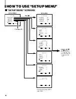
Страница 11: ...epending on the type of signal SET UP MENU Items Functions 1 FUNCTION SETTING Selects the control systems for the COLOR SYSTEM synchronized signal RUSH DELAY TIME tally lamp colors and MAKE TRIGGER terminal Checks the amount of time that the monitor has been used Selects the audio channel group for the EMBEDDED AUDIO When an input card compliant with EMBEDDED AUDIO is installed 2 PICTURE SUB ADJ C...

Страница 12: ...nction is only available when reset is displayed in the MENU BASIC MENU OPERATIONS MAIN MENU SET UP MENU cont d 7 DISPLAYINGTHE MENU SCREENS To display MAIN MENU Press the MENU button on the front panel To display SET UP MENU Press the button while pressing the button on the front panel NOTES To exit the MENU press the MENU button several times The MENU automatically exits about 30 seconds after t...

Страница 13: ... ZOOM ON ASPECT SELECT 4 3 SAFETY MARKER 80 R MARKER SELECT LINE R ZOOM OFF R ASPECT SELECT 13 9 R SAFETY MARKER 80 EXIT MENU ADJUST SELECT COLOR MATRIX SELECT MANUAL R Y PHASE 90 R B GAIN 0 86 G Y PHASE 244 G B GAIN 0 30 sub menu reset EXIT MENU ADJUST SELECT Some items are not displayed depending on the picture input signal See page 11 Adjusts with and buttons See page 12 for more information on...

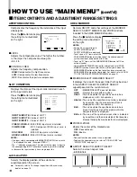
Страница 14: ...M H SIZE and ZOOM V SIZE on page 19 7 ASPECT SELECT R ASPECT SELECT Selects the screen aspect ratio 4 3 13 9 14 9 HOW TO USE MAIN MENU cont d 7 ITEM CONTENTS AND ADJUSTMENT RANGE SETTINGS 4 3 14 9 13 9 APERTURE CONTROL LEVEL 00 CONTROL FREQ HIGH sub menu reset EXIT MENU ADJUST SELECT SLOT CONDITION INPUT A VIDEO 1 INPUT B VIDEO 2 INPUT C COMPO INPUT D RGB INPUT E NO SLOT INPUT F NO SLOT EXIT MENU ...

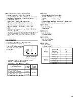
Страница 15: ...he standard setting is set to ITU601 or ITU709 depending on the input signal format The factory preset of MANUAL is ITU709 Input Signal Format Standard Manual setting setting MANUAL NTSC PAL 480 60i ITU601 480 60p 576 50i 575 50p ITU709 720 50p 720 60p 1080 50i ITU709 1080 60i 1035 60i 1080 24psF The menu screen when MANUAL is selected R Y PHASE 90 ITU601 R B GAIN 0 79 G Y PHASE 244 G B GAIN 0 45 ...

Страница 16: ...V SIZE 00 V POSITION 00 ZOOM H SIZE 00 ZOOM V SIZE 00 sub menu reset EXIT MENU ADJUST SELECT FUNCTION SETTING COLOR SYSTEM AUTO SYNC SELECT INT RUSH DELAY TIME STD TALLY SELECT GREEN REMOTE SYSTEM MAKE E AUDIO GROUP 1G HOUR METER X100h 000 EXIT MENU ADJUST SELECT PICTURE SUB ADJ CONTRAST 00 BRIGHT 00 CHROMA 00 PHASE 00 NTSC SETUP 00 COMPO LEVEL SMPTE sub menu reset EXIT MENU ADJUST SELECT DISTORTI...

Страница 17: ... control rush current 7 TALLY SELECT Selects the color of the tally lamp when lit on the upper front panel GREEN The tally lamp lights in green RED The tally lamp lights in red 7 REMOTE SYSTEM Selects the control system for the MAKE TRIGGER terminals Refer to HOW TO USE THE MAKE TRIGGER TERMINAL on page 21 MAKE make contact TRIGGER trigger contact 7 E AUDIO GROUP Selects the audio channel group fo...

Страница 18: ...ent signal s input level settings Press the button to display the setting menu illustrated on the right NOTE When the RGB signal is input only CONTRAST and BRIGHT are displayed When the PAL signal is input only CONTRAST BRIGHT and CHROMA are displayed 7 CONTRAST 20 00 20 7 BRIGHT 20 00 20 7 CHROMA 20 00 20 7 PHASE 20 00 20 7 NTSC SETUP Sets the set up level of the input NTSC signal 00 Compliant wi...

Страница 19: ...urns the picture counterclockwise SIZE POSI ADJ Adjusts the size or position of the picture Press the button to display the setting menu illustrated on the right 7 H SIZE Adjusts the horizontal screen size 20 00 20 Reduces the screen size horizontally Enlarges the screen size horizontally Reduced to 00 20 during the under scan mode 7 H POSITION Adjusts the horizontal screen position 20 00 20 Move ...

Страница 20: ...ing to appear on the screen for approx 3 seconds all reset Resets all SET UP MENU items to factory preset values 1 Select all reset by buttons then press button Confirmation message is displayed 2 To initialize press button To cancel the initialization press the MENU button STATUS DISPLAY Sets the status display ON OFF Switches the display on and off Also selects the type of display Press the butt...

Страница 21: ...o INPUT E Invalid Valid 7 Changes the input to INPUT F Invalid Valid 8 COLOR OFF Off On 9 AREA MARKER Off On 10 ASPECT Off On 11 TALLY SELECT GREEN RED 12 AREA MARKER set up without R with R 3 13 STATUS DISPLAY ON OFF 14 External Control Invalid Valid 2 15 GND 1 The TRIGGER trigger contact system switches each setting by instantaneously approx 1 second short circuiting short with GND of 15th termi...

Страница 22: ...he Monitor The monitor receives the data when DSR remains ON high and CTS is set to ON During Communication from the Monitor to the PC The monitor sends the data when both DSR and DCD are set to ON and RTS is set to ON Communication Procedures The following is the communication procedures 1 Starting the communication Receives the connection command BCN1Cr from the PC Sends the monitor s status BOK...

Страница 23: ... Turn on the power of the connected component and set it correctly Select the correct input with the INPUT SELECT buttons Check that the input signal format corresponds to the installed input card format Follow the procedures in SELF CHECK INDICATIONS Connect the audio cable firmly Set the connected component correctly Adjust the speaker volume with the VOLUME volume adjustment buttons Set each pi...

Страница 24: ...ction When a bright still image such as a white cloth is displayed for a long period it may appear to be colored This is due to the structure of the cathode ray tube and will disappear when another image is displayed You may sometimes experience a mild electric shock when you touch the picture tube This phenomenon is due to a normal buildup of static electricity on the CRT and is not harmful The m...

Страница 25: ...T A through F buttons will blink and the monitor s power automatically turns off If this happens follow the steps below and contact your dealer to resolve the problem 1 Check which indicators are blinking 2 Turn off the main power switch on the back of the monitor 3 Disconnect the Power Cord from the AC outlet 4 Contact your dealer with the information about which indicators are blinking NOTE If y...

Страница 26: ...x 1 7Environmental Conditions Operating temperature 5 C 35 C 41 F 95 F Operating humidity 20 80 non condensing 7Power Requirements 120 V AC 50Hz 60 Hz 7Power Consumption when input card is inserted 1 56 A Max 1 85 A 7Dimensions Width 395 mm 15 5 8 Height 334 mm 13 1 4 Depth 466 5 mm 18 3 8 not including wide mask and input card 7Weight 23 7 kg 52 1 lbs not including wide mask and input card 7Acces...

Страница 27: ...0p 720p 1080 50i 1080 60i 1125i 1035 60i 1125i 1 1080 24psF EMBEDDED AUDIO Input possible Pre set 䡬 Input possible Not pre set Input impossible 1 1035 60i 1125i is not pre set To input signals of these types some setup adjustments are required BT YA701P BT YA702P 䡬 BT YA703P BT YA705G 䡬 7 Compliant Signal Formats of Each Input Card ...

Страница 28: ...0068 323 436 3500 Government Marketing Department 52 West Gude Drive Rockville MD 20850 301 738 3840 Broadcast PARTS INFORMATION ORDERING 9 00 a m 5 00 p m EST 800 334 4881 24 Hr Fax 800 334 4880 Emergency after hour parts orders 800 334 4881 TECHNICAL SUPPORT Emergency 24 Hour Service 800 222 0741 Panasonic Canada Inc 5770 Ambler Drive Mississauga Ontario L4W 2T3 905 624 5010 Panasonic de Mexico ...

Отзывы: