8
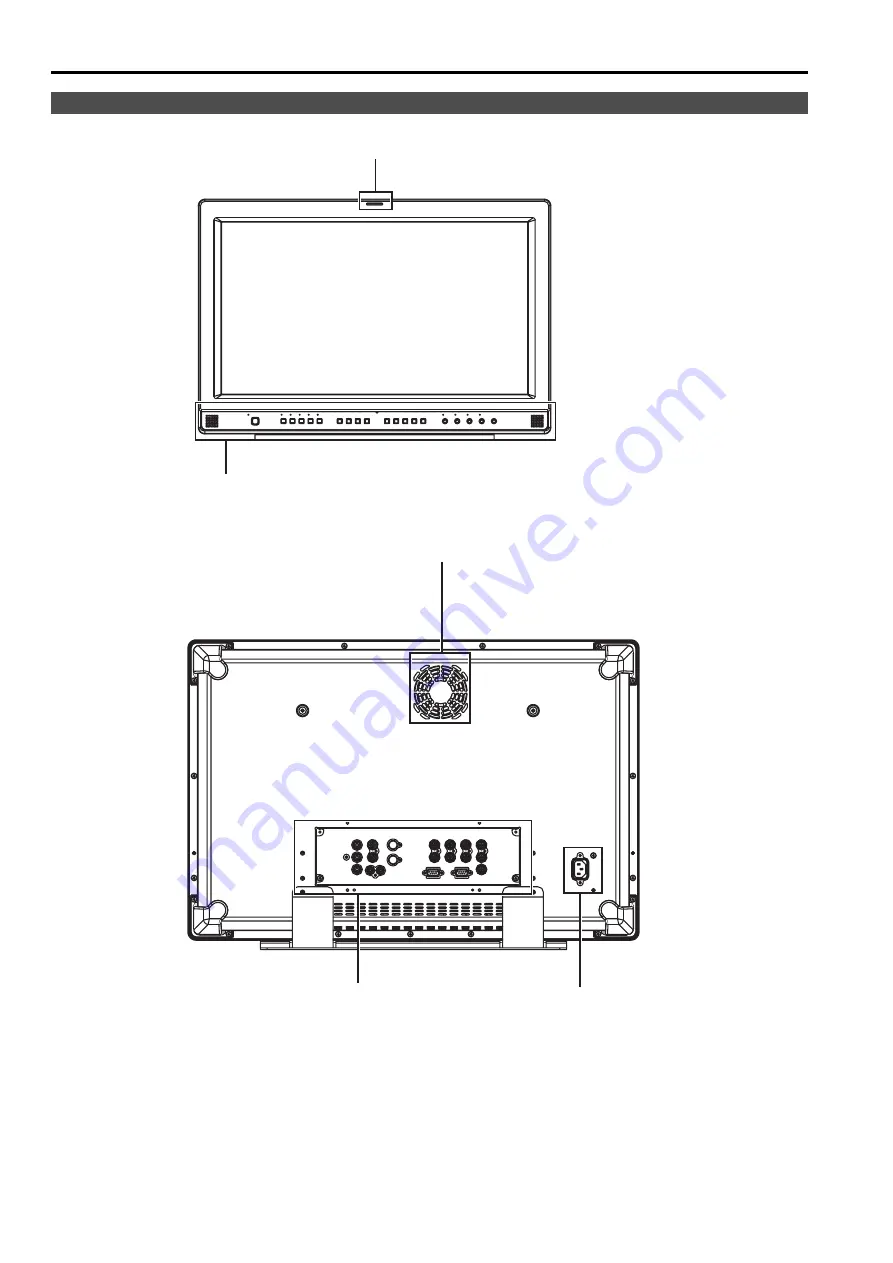
Video monitor unit
Front view
Rear view
Rear panel (
J
page 10)
Power supply (
page 11)
Front panel (
page 9)
Fan (
page 21)
Tally (
page 26, 30)
Controls and Their Functions
Страница 1: ...ating Instructions LCD Video Monitor BT P Model No BT E S0506M0 H Printed in Japan VQT0X79 ENGLISH D Before operating this product please read the instructions carefully and save this manual for future use ...
Страница 2: ...ING LIQUIDS AND DO NOT PLACE ANY LIQUID CONTAINERS ON TOP OF THE EQUIPMENT CAUTION In order to maintain adequate ventilation do not install or place this unit in a bookcase built in cabinet or any other confined space To prevent risk of electric shock or fire hazard due to overheating ensure that curtains and any other materials do not obstruct the ventilation CAUTION TO REDUCE THE RISK OF FIRE OR...
Страница 3: ... of North America One Panasonic Way Secaucus NJ07094 Support contact Panasonic Broadcast Television Systems Company 1 800 524 1448 This device complies with Part 15 of FCC Rules Operation is subject to the following two conditions 1 This device may not cause harmful interference and 2 this device must accept any interference received including interference that may cause undesired operation To ass...
Страница 4: ...To reduce the risk of electric shock do not remove covers No user serviceable parts inside Refer servicing to qualified service personnel CAUTION THE AC RECEPTACLE MAINS SOCKET OUTLET SHALL BE INSTALLED NEAR THE EQUIPMENT AND SHALL BE EASILY ACCESSIBLE TO COMPLETELY DISCONNECT THIS EQUIPMENT FROM THE AC MAINS DISCONNECT THE POWER CORD PLUG FROM THE AC RECEPTACLE WARNING TO REDUCE THE RISK OF FIRE ...
Страница 5: ...lier for further information Information on Disposal in other Countries outside the European Union This symbol is only valid in the European Union If you wish to discard this product please contact your local authorities or dealer and ask for the correct method of disposal FOR U K ONLY This appliance is supplied with a moulded three pin mains plug for your safety and convenience A 13 amp fuse is f...
Страница 6: ...herwise deteriorate the cabinet or damage the liquid crystal screen The unit is not compatible with the VESA mount When installing keep the display 10 cm 4 inches or more away from the back wall and surrounding objects Contents Read this first for BT LH2600WP 2 Read this first for BT LH2600WE 4 Precautions for Use 6 Standard accessories 6 Outline 7 Dimensions 7 Controls and Their Functions 8 Video...
Страница 7: ...en into two windows and compare the windows using the same input terminal and same format Furthermore you can display a still image or WFM on one of the windows J page 21 SUB WINDOW page 24 About the SUB WINDOW page 25 About WFM g PIXEL TO PIXEL function You can use the actual pixel count for picture confirmation when the input is an HD signals J page 25 About PIXEL TO PIXEL and PIXEL POS g REMOTE...
Страница 8: ...8 Video monitor unit Front view Rear view Rear panel J page 10 Power supply J page 11 Front panel J page 9 Fan J page 21 Tally J page 26 30 Controls and Their Functions ...
Страница 9: ... 0 60 30 BRIGHT 0 60 30 CONTRAST 0 60 50 BACKLIGHT 0 60 60 denotes factory preset values A rotating knob that can be pushed to operate When the picture adjusting knob is pressed its status is displayed and adjustment becomes possible The setting values are saved by pushing the knob again When values are changed from the factory preset values the LED above the knob amber lights The setting values a...
Страница 10: ...rminal OUT This is the YPBPR RGB input signal through out terminal When using the RGB signal you can also connect the external synchronizing signal to the SYNC HD terminal When using a PC RGB signal connect the horizontal synchronizing signal to the SYNC HD terminal and the vertical synchronizing signal to the VD terminal VD IN input terminal This is the vertical synchronizing signal VD input term...
Страница 11: ...r outlet Connecting and fixing the power cord for the U S A and Canada Power cord hook Using the power cord hook and the screw attach the power cord to the monitor unit Power cord Screw Connecting and fixing the AC mains lead for others AC mains lead hook Using the AC mains lead hook and the screw attach the AC mains lead to the monitor unit AC mains lead Screw Power Supply ...
Страница 12: ... is no input signal 4 Various display lock setting Displayed when control lock is ON Note UNSUPPORT SIGNAL and NO SIGNAL may not be displayed correctly Picture adjusting knob J page 9 This knob can be rotated and pushed The status display appears when the knob is pushed The display disappears when the knob is pushed again or if the knob is not operated for 10 seconds Settings can only be adjusted ...
Страница 13: ...tch the level display on and off and set the number of displayed channels using the menu The 0 dB line and channel display can be switched on and off from the menu This is displayed when the menu is used The display disappears if remains idle for 2 minutes The display position can be changed J page 21 MENU POSITION Function display F1 MARKER F2 WFM F3 LEVEL METER F4 PIXEL TO PIXEL F5 PIXEL POS XXX...
Страница 14: ...h to select the setting values then push ENTER Push MENU to cancel To return to the previous screen Push MENU Menu operations MENU FUNCTION HOURMETER MAIN MENU MARKER MARKER 16 9 4 3 BACK CENTER GPI PRESET1 GPI PRESET2 OFF OFF OFF NORMAL OFF 4 3 4 3 SET MARKER MARKER 16 9 4 3 BACK MARKER GPI PRESET1 GPI PRESET2 ON OFF OFF NORMAL OFF 4 3 4 3 SET How to Use the On Screen Menu continued ...
Страница 15: ...d push ENTER The user data is saved 1 Push MENU to display the MAIN menu 2 Push to select the SYSTEM CONFIG menu and push ENTER 3 Push to select the SETUP LOAD sub menu and push ENTER The setting values in the sub menu change to green 4 Push to select the file you wish to load to from USER1 USER5 then push ENTER The following screen appears To return to the factory preset setting values select FAC...
Страница 16: ...ROL GPI1 GPI2 GPI3 GPI4 GPI5 GPI6 GPI7 GPI8 VIDEO Y C NTSC SETUP YPBPR RGB COMPONENT LEVEL RGB SYNC COMP AUTOSETUP H POSITION V POSITION PHASE CLOCK WXGA XGA AUDIO INPUT SELECT EMBEDDED SELECT L EMBEDDED SELECT R LEVEL METER 0 dB POINT CH CONTROL LOCAL ENA OPERATION LCD FAN CONTROL HOURMETER WHITE BALANCE VAR1 3 MARKER 16 9 4 3 BACK CENTER GPI PRESET1 GPI PRESET2 FUNCTION1 FUNCTION2 FUNCTION3 FUNC...
Страница 17: ...tio setting is 4 3 OFF Marker not displayed 95 95 Area marker 90 90 Area marker 80 80 Area marker 93 93 Area marker 88 88 Area marker BACK 2 NORMAL HALF BLACK Used to select the background brightness excluding the marker NORMAL Normal background HALF Background brightness 50 BLACK Background brightness 0 Black CENTER 2 OFF ON Used to display the center marker OFF Not displayed ON Displayed GPI PRE...
Страница 18: ...th a 16 9 aspect ratio A dotted line is displayed as the marker You can display 4 3 marker at the same time as 16 9 marker Simultaneously display example The section becomes the MARKER BACK item The background selected with the 16 9 marker is controlled g Center marker Types of MARKER 4 3 marker 13 9 marker 14 9 marker VISTA marker CNSCO marker VISTA marker CNSCO marker 95 Area marker 93 Area mark...
Страница 19: ...M COLOR TEMP USER0 63 5 D93 D65 D56 VAR1 VAR2 VAR3 Used to select the color temperature USER0 63 Adjustable settings 0 63 color temperature around 3000K 9300K D93 Color temperature around 9300K D65 Color temperature around 6500K D56 Color temperature around 5600K VAR1 WB adjustment mode 4 VAR2 WB adjustment mode 4 VAR3 WB adjustment mode 4 SHARPNESS MODE 2 HIGH 3 LOW Used to select the width of th...
Страница 20: ...color temperature that will become the basis for adjustments USER0 63 Adjustable settings 0 63 color temperature around 3000K 9300K D93 Color temperature around 9300K D65 Color temperature around 6500K D56 Color temperature around 5600K GAIN RED 0 511 Factory presets are values for color temperature D65 The presets are values adjusted before shipment from factories GAIN elements for RED are adjust...
Страница 21: ...om left of the screen RB Bottom right of the screen RT Top right of the screen LT Top left of the screen ROTARY POSITION CENTER LB RB RT LT Used to set the picture adjusting knob status on screen menu display position CENTER Center of the screen LB Bottom left of the screen RB Bottom right of the screen RT Top right of the screen LT Top left of the screen STATUS DISPLAY CONTINUE 3SEC OFF OFF Used ...
Страница 22: ...GAMMA SELECT Used to display the gamma curve The display changes in the following order GAMMA STANDARD J GAMMA FILM J GAMMA STDIO PST J GAMMA STANDARD SD ASPECT Used to switch between 16 9 and 4 3 1 SCAN You can switch between UNDER SCAN and NORMAL SCAN 1 SUB WINDOW You can perform the settings for 2 screen display mode 1 The display changes in the following order SINGLE J FULL PARTJ STILLJ SINGLE...
Страница 23: ...ALID FUNCTION is displayed and the setting is disabled When SUB WINDOW still picture or HD display including PIXEL TO PIXEL is on INVALID FUNCTION is displayed and the setting is disabled SCAN When GPI item is set INVALID FUNCTION is displayed and the setting is disabled In SUB WINDOW or PIXEL TO PIXEL mode INVALID FUNCTION is displayed and the setting is disabled SUB WINDOW When YPBPR RGB set in ...
Страница 24: ... sub window left side still image becomes blurred and blanking occurs However if the same format signals are input into the input terminal when acquiring the still image the images will be displayed correctly FULL The main window is reduced and made into 2 sub window sub window sub window Normal window main window Before inputting the image sub window sub window After inputting the image sub windo...
Страница 25: ...the PIXEL TO PIXEL function PIXEL TO PIXEL and PIXEL POS must be assigned to any two of the buttons FUNCTION1 to FUNCTION5 The underlined values are factory preset setting values 1 When PIXEL TO PIXEL is on the following menu settings become invalid ON for ANAMO and UNDER for SCAN set in VIDEO CONFIG Various HV DELAY settings in FUNCTION MARKER display 2 When the input signal is SDI1 SDI2 or YPBPR...
Страница 26: ... when anything other than RGB VIDEO is selected in YPBPR RGB in the INPUT SELECT menu MONO operation when input signal is PC GPI Sub menu Settings Explanation GPI CONTROL DISENABLE ENABLE GPI functions enable disenable settings GPI1 GPI8 UNDEF MARKER1 ON OFF MARKER2 ON OFF MARKER BACKHALF MARKER BACKBLACK CENTER MARKER INPUT SEL VIDEO INPUT SEL Y C INPUT SEL SDI1 INPUT SEL SDI2 INPUT SEL YPBPR RGB...
Страница 27: ... the PC RGB signal COMPONENT LEVEL SMPTE B75 B00 Selects YPBPR Component signal input level SMPTE When the signal level specified in SMPTE is Chroma 100 IRE PB PR 0 7 Vp p B75 Select this when connecting a betacam or simliar devices set to 7 5 IRE The inner parts of the monitor are set at 7 5 IRE setup level to suit the black level B00 Select this when connecting a betacam or similar devices that ...
Страница 28: ...AUTO ANALOG Used to select speaker output AUTO When SDI input line is selected with INPUT SELECT on the front panel embedded audio SDI terminal When an input line other than SDI1 and SDI2 is selected with INPUT SELECT on the front panel analog AUDIO input terminal ANALOG Analog AUDIO input terminal EMBEDDED SELECT L CH1 CH8 Factory preset setting CH1 Used to select the audio channel of the embedde...
Страница 29: ...factory preset setting values 3 Time is displayed in XX 4 Linked with the FAN MOTOR ON OFF status CONTROL Sub menu Settings Explanation CONTROL LOCAL REMOTE Used to select the operation Combined control lock LOCAL Front operation enabled REMOTE Remote operation enabled The front controls become locked 1 LOCAL ENA 2 DIS INPUT When REMOTE is selected in CONTROL this selects whether front controls ar...
Страница 30: ... ON Open OFF MARKER BACK HALF 2 Reduces the brightness of the background outside the marker displayed in GPI PRESET1 J page 17 by 50 Level operation Connected ON Open OFF MARKER BACK BLACK 2 Reduces the brightness of the background outside the marker displayed in GPI PRESET1 J page 17 to 0 Level operation Connected ON Open OFF CENTER MARKER Switches the center marker display ON OFF When other mark...
Страница 31: ...S 232C g Connectors and signal names Connector D SUB 9 pin female Signal name g Communication Conditions g Command format Commands are 3 characters following STX finally adding ETX Add a colon after the command as required and add the data g Response formats 1 Setting command response 2 Query command response 3 Error response Error code ER001 Invalid command ER002 Parameter error RS 232C terminal ...
Страница 32: ...88 MK103 93 MK104 95 MK105 14 9 MK106 13 9 MK107 4 3 MK108 90 MK109 CNSCO MK110 VISTA 4 3 marker MK200 OFF MK201 80 MK202 88 MK203 93 MK204 95 MK208 90 Marker background BAK0 NORMAL BAK1 HALF BAK2 BLACK Center marker CMK0 OFF CMK1 ON DMK 9 MGM Gamma selection 1 STANDARD 2 FILM 3 STDIO PST MGM 10 MCT Color temperature settings 00 D56 01 D65 02 D93 03 VAR1 04 VAR2 05 VAR3 10 73 USER0 63 MCT 11 VPC S...
Страница 33: ...e 00 D56 01 D65 02 D93 03 VAR1 04 VAR2 05 VAR3 10 73 USER0 63 7 QPC Sharpness SHP Sharpness mode 0 LOW 1 HIGH SHH Horizontal sharpness value 00 30 SHV Vertical sharpness value 00 30 8 QIP IP mode 0 MODE1 1 MODE2 9 QMO Monochrome 1 OFF 2 ON 10 QAS Aspect 0 16 9 1 4 3 11 QSC Scan 0 NORMAL 1 UNDER 12 QAN Analog mode 0 YPBPR 1 RGB VIDEO 2 RGB COMP 13 QSY RGB sync 0 G ON 1 EXT 14 QFR Format 00 NO SIGNA...
Страница 34: ... if a malfunction occurs it is essential that general servicing and maintenance servicing are conducted on a regular basis to prevent malfunctions and accidents caused by the deterioration of consumable parts and to keep the monitor working normally 2 Standard maintenance time guidelines and items to be performed The following maintenance performance times give standard guidelines for when to perf...
Страница 35: ... VIDEO 1 line BNC x 2 1 connector with through out configuration Y C 1 line Y C connector x 2 1 connector with through out configuration Analog component 1 line for YPBPR RGBS BNC x 8 4 connectors with through out configuration However when input is RGB COMP this becomes BNC x 5 R G B HD and VD Through out is not available SDI 2 line BNC x 3 1 connector with switched out configuration Audio input ...
Страница 36: ...ct to change without notice Input signal formats VIDEO Y C SDI1 SDI2 YPBPR RGB VIDEO RGB COMP NTSC PAL 480 59 94I 480 59 94P 576 50I 576 50P 720 50P 720 59 94P 720 60P 1035 59 94I 1 1 1 1 1035 60I 2 2 2 2 1080 23 98PsF 1080 24PsF 1080 23 98P 1080 24P 1080 25P 1080 29 97P 1080 30P 1080 50I 1080 50P 1080 59 94I 1080 60I 1080 59 94P 1080 60P 640 x 400 70Hz 640 x 480 60Hz 640 x 480 75Hz 640 x 480 85Hz...
Страница 37: ...37 MEMO ...
Страница 38: ...Panasonic Way 2E 10 Secaucus NJ 07094 201 348 7587 Broadcast PARTS INFORMATION ORDERING 9 00 a m 5 00 p m EST 800 334 4881 24 Hr Fax 800 334 4880 Emergency after hour parts orders 800 334 4881 TECHNICAL SUPPORT Emergency 24 Hour Service 800 222 0741 Panasonic Canada Inc 5770 Ambler Drive Mississauga Ontario L4W 2T3 905 624 5010 Panasonic de Mexico S A de C V Av angel Urraza Num 1209 Col de Valle 0...