background image

-1-

CONTENTS

FEATURES .................................................................................................................................................................................. 2

PRECAUTIONS ........................................................................................................................................................................... 3

MAJOR OPERATING CONTROLS AND THEIR FUNCTIONS  ..................................................................................................... 4

FRONT PANEL  .................................................................................................................................................................... 4

REAR PANEL ........................................................................................................................................................................ 6

INSTALLATION OF PAN/TILT HEAD ........................................................................................................................................... 8

CONNECTION ............................................................................................................................................................................. 11

OPERATION ................................................................................................................................................................................ 15

RACK MOUNTING  ...................................................................................................................................................................... 23

SPECIFICATIONS ........................................................................................................................................................................ 24

ACCESORIES .............................................................................................................................................................................. 25

Содержание AWHB505 - MULTIPORT HUB

Страница 1: ...Multiport Hub AW HB505 Before attempting to connect or operate this product please read these instructions completely ...

Страница 2: ...tning flash with arrowhead sym bol within an equilateral triangle is intended to alert the user to the pres ence of uninsulated dangerous voltage within the product s enclosure that may be of sufficient magnitude to constitute a risk of electric shock to persons The exclamation point within an equilat eral triangle is intended to alert the user to the presence of important operating and maintenanc...

Страница 3: ...NTS FEATURES 2 PRECAUTIONS 3 MAJOR OPERATING CONTROLS AND THEIR FUNCTIONS 4 FRONT PANEL 4 REAR PANEL 6 INSTALLATION OF PAN TILT HEAD 8 CONNECTION 11 OPERATION 15 RACK MOUNTING 23 SPECIFICATIONS 24 ACCESORIES 25 ...

Страница 4: ...ght cable UTP category 5 and the Multiport Hub connected to each camera and pan tilt head with three coaxial cables 5C 2V and a single 10BASE T Straight cable UTP category 5 various kinds of control can be performed on the cameras and pan tilt heads and camera video signals and genlock signals can be sent and received The maximum cable length from the Multi Hybrid Control Panel to the Multiport Hu...

Страница 5: ...e power cable connection or disconnection Be sure to switch power off before connecting or dis connecting the power cable Avoid outdoor use Install the control panel more than 1 meter away from the monitors Care Pull out the power cable plug and wipe the control panel clean with a dry cloth If it is extremely dirty dip a cloth into a diluted solution of kitchen detergent squeeze it hard and wipe t...

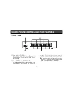
Страница 6: ...oes out when the same switch is set to the OFF position w Power ON OFF Switch POWER ON OFF The camera and pan tilt head are switched on when this switch is set to the ON position The POWER indi cator lights The camera and pan tilt head are partial ly switched off when this switch is set to the OFF posi tion Note This switch must be set to the ON position in advance in controlling the cameras and p...

Страница 7: ...e Multi Hybrid Control Panel back to the OFF posi tion Note Turning this control changes not only the Y sig nal level but also the entire video level r Cable Compensation Chrominance Control CABLE COMP C Used to adjust the C chrominance signal level of video output signals as appropriate to the length of the cable between the pan tilt head and the Multiport Hub First select a camera with the Contr...

Страница 8: ...y y Pan tilt Control Input Connector TO CONTROL PANEL PAN TILT HEAD CONTOROL IN RJ 45 8 pin Modular Jack Connect it to Pan tilt Control Output Connector P T CONTROL OUT on the multi hybrid control panel with a 10BASE T straight cable UTP category 5 or equiva lent which may be extended up to 10 meters u Preview Video Output Connector TO CONTROL PANEL PREVIEW OUT BNC Connector Connect it to Preview ...

Страница 9: ...T BNC Connector Connect one of 1 to 5 HEAD G L OUT Connectors to Genlock Signal Input Connector G L IN on the cor responding camera and pan tilt head with a coaxial cable 5C 2V or equivalent The maximum allowable cable length is 500 meters 3 Camera Control Output Connector TO CAMERA PAN TILT HEAD CAMERA CONTROL OUT Connect one of 1 to 5 Camera Control Output Connectors to Camera Control Signal Inp...

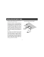
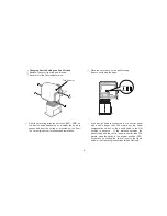
Страница 10: ...t through the wire hole opened in a firm board such as of the ceiling for example and fasten it securely The switches on the pan tilt head have been preset before shipment from the factory on the assumption that the pan tilt head would be suspended from the ceiling If the pan tilt head is mounted on a board for example be sure to shift the mounting direction switch es on the pan tilt head Unless t...

Страница 11: ... the cover back on the pan tilt head Be sure not to trap the wires If the pan tilt head is connected to the control panel with a cable longer than 300 meters set the cable compensation switch on the pan tilt head to the ON position in advance If the distance between the pan tilt head and the control panel is shorter than 300 meters keep the switch in the original position OFF For details on shifti...

Страница 12: ... compen sation switch to the ON position by observing the fol lowing procedure q Remove the controller connection panel from the pan tilt head Be careful of the wires w Shift the cable compensation switch on the inner side of the controller connection panel of the pan tilt head to the ON position e Place the controller connection panel back on the pan tilt head ...

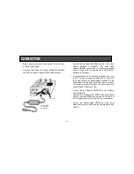
Страница 13: ... nominal cross sec tion of 1 25 mm2 or larger that meets the UL specifica tions and connect the Pan tilt Head AW PH300 to the Pan tilt Head AC Adaptor AW PS300 with that cable The maximum distance between the pan tilt head and pan tilt head AC adapter is 30 m Connect the AC Adapter AW PS505 to the Multiport Hub AW HB505 Connect the AC Adaptor AW PS301 to the Multi Hybrid Control Panel AW RP505 and...

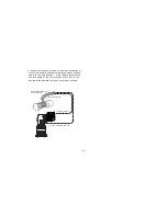
Страница 14: ...he iris control cable of the motor driven zoom lens to the camera and the remote zoom focus control cable to the pan tilt head If the remote zoom focus control cable of the motor driven zoom lens is con nected to the camera the lens cannot be controlled To Lens Interface Connector To Iris Connector Iris Control Cable Remote Zoom Focus Control Cable ...

Страница 15: ...el with the three coaxial cables video signal G L signal camera control signal and one 10BASE T straight cable pan tilt head control signal The maxi mum distance between the control panel and pan tilt head is 10 meters for coaxial cables 5C 2V and 10BASE T straight cable UTP category 5 or equiva lent Connect the multiport hub to the multi hybrid control panel with the three coaxial cables video si...

Страница 16: ... WIP EXT ND OP H F 1 2 3 4 G L P H A S E PRESE T T PED M u l t i H y b r i d C o n t r o l P a n e l A W R P 5 0 5 1 5 4 3 2 1 5 4 3 2 2 1 3 4 5 6 7 8 9 1 0 9 0 180 0 27 0 LEVEL TALLY CONTROL POWER 1 Y C 2 Y C 3 Y C 4 Y C 5 Y C OFF ON C A B L E C O M P M u l t l P o r t H u b A W H 8 5 0 5 POWER ON OFF Color Monitor WV CM 1470 PUSH POWER ON OFF Color Monitor WV CM 1470 PUSH POWER ON OFF Color Moni...

Страница 17: ...n head operation limiter data can not be properly stored in the memory For details on shifting these switches refer to INSTALLATION OF PAN TILT HEAD at page 8 or the Operating Instructions for Pan tilt Head q Select a pan tilt head with the CONTROL switch on the multi hybrid control panel w Left Panning Limiter Turn the pan tilt head to the desired left panning limit with PAN TILT Lever of the mul...

Страница 18: ...ti hybrid control panel keep MEMORY Switch depressed and simultaneously press buttons 7 and 8 of PRESET Switch for 5 sec onds or more When the desired limit has been set button 5 of PRESET Switch lights To reset the limit keep the MEMORY switch depressed and simultaneously press buttons 7 and 8 of PRESET Switch again for 5 seconds or more When the set limit is reset button 10 of PRESET Switch ligh...

Страница 19: ... tilt head number 1 to 5 set the video output connector on the control panel set the mode switch to the BAR position then observe the color bar signals e Adjust the Y luminance signal level with the CABLE COMP Y control for the corresponding camera pan tilt head number 1 to 5 then adjust the CABLE COMP Y control then adjust the C chrominance sig nal level with CABLE COMP C control Repeat this unti...

Страница 20: ...mera No G L adjustment is necessary in case of no genlock Horizontal Phase Adjustment q Set G L PHASE ON OFF Switch of the multi hybrid con trol panel to the ON position Note When G L PHASE ON OFF Switch of the multi hybrid control panel is set to the ON position the sync phase of the camera changes to the settings of G L PHASE H Control G L PHASE Coarse Switch and G L PHASE SC Control Unless G L ...

Страница 21: ...G L PHASE SC Control to match the subcarrier color phase of the video signal output with that of the reference tone such as of the program output split color bar output of a Color Special Effect Generator for example Higher accuracy can be obtained if a vectorscope is used for color phase adjustment ON SC H OFF G L P H A S E 90 180 0 270 External genlock input signal black burst sig nal Video sign...

Страница 22: ...ONTROL switch on the multi hybrid control panel 2 Select a camera with the CONTROL switch on the multi hybrid control panel White balance adjustment is necessary when using the camera for the first time or if the camera has not been used for a long period of time Once the white balance is adjusted no readjustment is necessary if the camera is used under the same condi tions Automatic White Balance...

Страница 23: ...ture Black balance adjustment is necessary when using the camera for the first time or if the camera has not been used for a long period of time Black balance adjustment is necessary if there is a big change in the ambient temperature or at the turn of a season Once the black balance is adjusted no readjustment is necessary if the camera is used under the same conditions Automatic Black Balance Co...

Страница 24: ...RESET Switch flash press any of the buttons 1 to 10 of PRESET Switch as desired to store the data in the memory Only that button of PRESET Switches where the data is stored lights Note If data is stored again in the same button of PRESET Switches of the multi hybrid control panel the preceding data is deleted 4 Repeat Steps q and e to store the presettings of all the cameras and pan tilt heads in ...

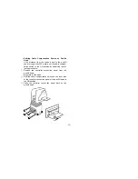
Страница 25: ... feet e With the rack mounting brackets on both ends of the multiport hub fasten them with the supplied screws 4 pcs r Mount the multiport hub in the rack and fasten it with the rack mounting screws 4 pcs Notes The rack mounting screws are optional Optional Keep the multiport hub away at least its size from other devices or mount a cooling fan in the rack so that the temperature inside the rack wi...

Страница 26: ...tor Genlock Output 75Ω x 5 BNC connector Camera Control Output Control signal x 5 BNC connector Pan tilt Control Output Control signal x 5 RJ 45 8P modular jack Switches Power ON OFF Switch Controls CABLE COMP Y Control CABLE COMP C Control Pan tilt Head Connecting Cable x 4 Coaxial Cable 3 pcs 10BASE T straight cable 1 pc In case of using G L function Control Panel Connecting Cable pan tilt head ...

Страница 27: ... 250 D mm 16 9 16 W x 3 7 16 H x9 13 16 D Weight 4 kg 8 8 lbs Finish Cover AV Ivory vinyl chloride steel Panel AV Ivory painting Weight and dimensions indicated are approximate Specifications are subject to change without notice ACCESSORIES Rack mounting part 2 Mounting screws 4 ...

Страница 28: ...GA 30174 Panazip 11 770 338 6841 fax 770 338 6741 Law Enforcement Video Products 1225 Northbrook Parkway Suite 1 160 Suwanee GA 30174 Panazip 11 770 338 6844 fax 770 338 6721 WESTERN ZONE Los Angeles Region 6550 Katella Ave 17A 1 Cypress CA 90630 714 373 7271 Government Marketing Department 52 West Gude Drive Rockville MD 20850 301 738 3840 PANASONIC CANADA INC 5770 Ambler Drive Mississauga Ontari...

Отзывы: