– 166 –
Chapter 9 3G mode/4K mode — Difference of function for each mode
Notation of the terminal at rear
Notation in menu
Representative notation
21
[SDI IN21]
[SDI IN21]
22
[SDI IN22]
23
[SDI IN23]
24
[SDI IN24]
25
[SDI IN25]
[SDI IN25]
26
[SDI IN26]
27
[SDI IN27]
28
[SDI IN28]
29
[SDI IN29]
[SDI IN29]
30
[SDI IN30]
31
[SDI IN31]
32
[SDI IN32]
f
Status of all the input signals ([SDI IN1] to [SDI IN32]) are displayed in the <IN OUT> button
→
[SDI IN]
→
[Status] tab.
f
It is displayed with the representative notation gathering the signals for four lines input from outside to one for other menus (such as assigning setting
of the XPT button).
f
Signal from both 3G-SDI Level A and 3G-SDI Level B can be used in all input terminal. This cannot be used when there are signals in different formats
or asynchronous signals mixed in the signals of four lines constructing the 4K signal.
f
[Off] cannot be selected for the [FS] item in the <IN OUT> button
→
[SDI IN]
→
[Frame Buffer] tab
→
[SDI IN1] to [SDI IN29] column in the 4K mode.
f
[1080p Auto] can be selected for the [FS] item in the <IN OUT> button
→
[SDI IN]
→
[Frame Buffer] tab
→
[SDI IN1] to [SDI IN29] column.
Even when the video signal of the frame frequency (29.97p, 29.97Psf, 59.94i, 25p, 25Psf, 50i, 23.98p, 23.98Psf, 24p, 24Psf) that is different from the
system format is input in the terminal set to [1080p Auto], the screen does not become black.
f
The 4K signal format can be selected for the [4K Format] item in the <IN OUT> button
→
[SDI IN]
→
[Frame Buffer] tab
→
[SDI IN1] to [SDI IN29]
column.
-
AUTO: The format is determined by referencing the Payload ID contained in the input SDI signal. It is processed in 2SI format if all the signals for
four lines are 2SI format, and in SQD format if they are not.
-
SQD: It is processed in SQD format.
-
2SI: It is processed in 2SI format. All the signal for the four lines are converted to black signal if no signal is included in the signals for the four lines.
-
UC: The signal with smallest number within the signals of four lines is processed by enlarging to the size of 4K resolution.
f
The [Link] item in the <IN OUT> button
→
[SDI IN]
→
[Frame Buffer] tab
→
[SDI IN1] to [SDI IN32] column will display the status of Payload ID
contained in the input SDI signal.
It will display as “2SI‑#” (# is number) if it is 2SI format, and “―” if it is something else.
However, it will display as “ASYNC” if the signals with different synchronization is connected.
r
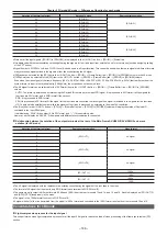
Relationship between the notation of the output terminals at the rear of the Main Frame AV‑HS60U1/AV‑HS60U2 and menu
notation (for 4K mode)
Notation of the terminal at rear
Representative notation
Video format
1
[SDI OUT1]
4K signal
2
3
4
5
[SDI OUT5]
4K signal
6
7
8
9
[SDI OUT9]
4K signal
10
11
12
13
[SDI OUT 13]
1080p
14
1080i
15
[SDI OUT 15]
1080p
16
1080i
f
The 4K signal is displayed with the representative notation consolidating the signals of the four lines in the menu.
f
The format of 4K signal that is output is only SQD format (each terminal is 3G-SDI Level B).
f
The same signal is output in different formats (1080p and 1080i) from the rear terminals 13 and 14, and 15 and 16. Each is displayed as [SDI OUT 13]
and [SDI OUT 15] respectively in the menu.
f
The signal in the 1080p format is output in 3G-SDI Level B.
f
A signal with half of the line decimated from the signal in 1080p format and converted to the 1080i format is output from the terminals 14 and 16.
Considerations for 4K mode
r
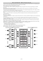
Light compression process for the input signal
This unit performs unique light compression process for all the input 4K signal to reduce the load of video processing of the frame synchronizer (FS)
section.
Содержание AV-HS60C1E
Страница 5: ...Please read this chapter and check the accessories before use Chapter 1 Overview ...
Страница 32: ...This chapter describes basic operations and matters to be performed prior to use Chapter 4 Preparations ...
Страница 52: ...This chapter describes menu operations Chapter 5 Basic Operations ...
Страница 118: ...This chapter describes the input output signal settings Chapter 6 Input Output Signal Settings ...
Страница 129: ...This chapter describes how to operate the CONFIG menu displayed when the CONF button is pressed Chapter 7 CONFIG Menu ...
Страница 140: ...This chapter describes how to operate the system menu displayed when the SYS button is pressed Chapter 8 System Menu ...
Страница 162: ...This chapter describes the difference with the Standard mode Chapter 9 3G mode 4K mode ...
Страница 168: ...This chapter describes the terminals and signals of the unit Chapter 10 External Interfaces ...
Страница 173: ...This chapter describes the dimensions and specifications of this product Chapter 11 Specifications ...
Страница 184: ...This chapter describes the setting menu table and terms Chapter 12 Appendix ...
Страница 206: ...Web Site http www panasonic com Panasonic Corporation 2014 ...


