– 159 –
Chapter 8 System Menu — Maintenance settings
10
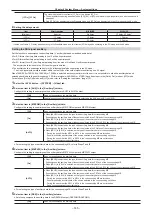
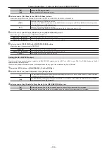
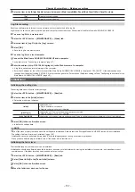
Confirm the status in the [License Status] column
→
[Primatte Key2] to [Primatte Key4]
f
Confirm that the item corresponding to the channel for the key where activation has been enabled is set to [Enable].
Maintenance
Confirmation of cumulative operating time
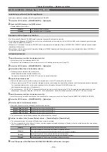
Confirm rough indication of the cumulative operating time of the Main Frame AV‑HS60U1/AV‑HS60U2, and the cumulative operating time of the power
supply and cooling fan installed in the Main Frame AV-HS60U1/AV-HS60U2 and the Control Panel AV-HS60C1/AV-HS60C2/AV-HS60C4.
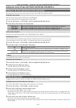
1
Select the <SYS> button
→
[MAINTENANCE]
→
[Mainte] tab
2
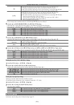
Confirm each item in the [System Running] column.
[System]
Displays the count-up time when the Main Frame AV-HS60U1/AV-HS60U2 is in operation.
3
Confirm each item in the [Main Frame Running] column.
[Power A]
Displays the count-up time when the power supply 1 of the Main Frame AV-HS60U1/AV-HS60U2 is in operation.
[Power B]
Displays the count-up time when the power supply 2 of the Main Frame AV-HS60U1/AV-HS60U2 is in operation.
[Fan]
Displays the count-up time when the Main Frame AV-HS60U1/AV-HS60U2 is in operation.
4
Confirm each item in the [Main Panel Running] column.
[Power A]
Displays the count-up time when the main control panel is connected to the <PANEL> terminal of the Main Frame
AV-HS60U1/AV-HS60U2, and the power supply 1 of the corresponding Control Panel AV-HS60C1/AV-HS60C2/
AV-HS60C4 is in operation.
[Power B]
Displays the count-up time when the main control panel is connected to the <PANEL> terminal of the Main Frame
AV-HS60U1/AV-HS60U2, and the power supply 2 of the corresponding Control Panel AV-HS60C1/AV-HS60C2/
AV-HS60C4 is in operation.
5
Confirm each item in the [Sub1 Connecting]/[Sub2 Connecting] column.
[Power A]
Displays the count-up time when the sub control panels 1/2 (the second and the third Control Panel AV-HS60C1/
AV-HS60C2/AV-HS60C4) are connected to the LAN terminal of the Main Frame AV-HS60U1/AV-HS60U2 and each
power supply 1 is in operation.
[Power B]
Displays the count-up time when the sub control panels 1/2 (the second and the third Control Panel AV-HS60C1/
AV-HS60C2/AV-HS60C4) are connected to the LAN terminal of the Main Frame AV-HS60U1/AV-HS60U2 and each
power supply 2 is in operation.
@
@
NOTE
t
When the unit with system version earlier than 3.00-00-0.00 is updated to 3.00-00-0.00 or later, each item in the [System Running] column, [Main
Frame Running] column, and [Main Panel Running] column will display the same value.
t
Each item in the [Main Panel Running]/[Sub1 Connecting]/[Sub2 Connecting] columns will display the value counted up in the Main Frame
AV-HS60U1/AV-HS60U2. Therefore, the displayed value will not change even if the main control panel or the sub control panel connected to the Main
Frame AV-HS60U1/AV-HS60U2 is replaced.
Initializing the Storage Module AV‑HS60D1
1
Select the <SYS> button
→
[MAINTENANCE]
→
[Mainte] tab.
2
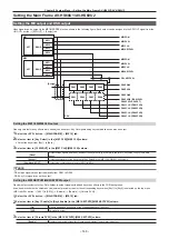
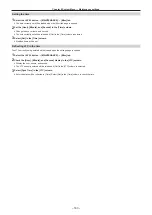
Select [SSD Format] in the [Format] column.
f
All data stored in the Storage Module AV-HS60D1 (optional) is initialized.
Setting the date and time
The date and time to be used as the time stamp of the memory card can be set. Make sure to set them when using a memory card. They can be
displayed on the split screens of the MultiView display.
Setting the date
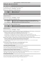
1
Select the <SYS> button
→
[MAINTENANCE]
→
[Misc] tab.
f
The date currently set will be loaded when the [Misc] tab page is opened.
2
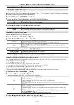
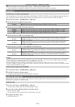
Select an item in [Year], [Month], and [Date] in the [Date] column.
f
Set the year, month, and day.
f
The date currently set will be reloaded if [Get] in the [Date] column is selected.
3
Select [Set] in the [Date] column.
f
Modified items will be set.
Содержание AV-HS60C1E
Страница 5: ...Please read this chapter and check the accessories before use Chapter 1 Overview ...
Страница 32: ...This chapter describes basic operations and matters to be performed prior to use Chapter 4 Preparations ...
Страница 52: ...This chapter describes menu operations Chapter 5 Basic Operations ...
Страница 118: ...This chapter describes the input output signal settings Chapter 6 Input Output Signal Settings ...
Страница 129: ...This chapter describes how to operate the CONFIG menu displayed when the CONF button is pressed Chapter 7 CONFIG Menu ...
Страница 140: ...This chapter describes how to operate the system menu displayed when the SYS button is pressed Chapter 8 System Menu ...
Страница 162: ...This chapter describes the difference with the Standard mode Chapter 9 3G mode 4K mode ...
Страница 168: ...This chapter describes the terminals and signals of the unit Chapter 10 External Interfaces ...
Страница 173: ...This chapter describes the dimensions and specifications of this product Chapter 11 Specifications ...
Страница 184: ...This chapter describes the setting menu table and terms Chapter 12 Appendix ...
Страница 206: ...Web Site http www panasonic com Panasonic Corporation 2014 ...

