background image

– 51 –

Chapter 5 Basic Operations — KEY

KEY

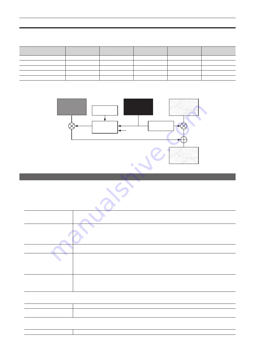
Combine the background image with another image. The key definition can be adjusted, and an edge can be added to the combined image.

The unit comes with four keys for each ME.

The functional differences between <KEY1>/<KEY2>/<KEY3>/<KEY4> buttons and <DSK1>/<DSK2>/<DSK3>/<DSK4> buttons are as follows.

Tab

<KEY1> button

<KEY2> button

<KEY3> button

<KEY4> button

<DSK1> to <DSK4> 

buttons

[PinP Adjust] (page 62)

3D compatible*

3D compatible*

2D compatible

2D compatible

Not possible

[Flying Key Adjust] (page 61)

3D compatible*

3D compatible*

Not possible

Not possible

Not possible

[Transition] (pages 53, 66)

[MIX]/[WIPE]

[MIX]/[WIPE]

[MIX]/[WIPE]

[MIX]/[WIPE]

[MIX]

[Key Pattern] (page 53)

[WIPE]/[SQ]/[SL]/[3D]

[WIPE]/[SQ]/[SL]/[3D]

[WIPE]

[WIPE]

[MIX] only

[Chroma] (page 55)

Standard

Option

Option

Option

Not possible

*  2D compatible in the version below V2.00.00. 3D will be available in V2.00.00 or higher.

The following shows how key combinations work.

ABC

ABC

Key fill

Key source

1

Output image

Background

Invert

Select

[Clean Key]

Selecting the key type

Set the key type on the Menu Panel AV-HS60C3.

Select the <ME1>/<ME2> button 

 [KEY1] to [KEY4] 

 [Key Setting] tab.

Select an item in [Type] in the [Key] column.


f

Select the method to generate key signals.

[Lum]

(luminance key/self key)

Creates key signals from luminance components or luminance and chroma components of key fill signals.


f

Since the luminance key is operated as a self key, the key fill signals are used as the key source signals.

The key signals do not change even when the key source signals are switched.

[Linear]

(linear key)

Creates key signals from luminance components of key source signals. It is used when the key source signal and key fill 

signal are different.
Use source with a black background and white characters or shape to be combined by the key as the key source signal. 
Source which is not black and white may not be combined clearly. Source with white background and black characters 
can be used by inverting the keys with the key invert function.

[Chroma]

(chroma key)

Creates key signals using a specific hue of key source signals as the reference.

[Full]

(full key)

Creates key signals using the images on the full screen as the key source signals. When used in combination with the 

flying key, it can create a PinP composition.

For details, refer to “Flying key” (page 61).


f

For the full key, the images on the full screen are used as the key source signals.

The key signals do not change even when the key source signals are switched.

[PinP]

(picture in picture/full key)

Combines the background image with a resized key fill.

For details, refer to “PinP (Picture in Picture)” (page 62).


f

For the full key, the images on the full screen are used as the key source signals.

The key signals do not change even when the key source signals are switched.

Select an item in [Lum Key] in the [Key] column.

[Chroma Off]

Generates the key signals only from the luminance components.

[Chroma On]

Generates the key signals considering the chroma components in addition to the luminance components. This item is set 
when a low luminance component color is used for key signals such as when cutting blue characters.

Select an item in [Clean Key] in the [Key] column.

[Off]

Cuts key fill with a key signal.

Содержание AV-HS6000

Страница 1: ...J51A E W0214NN0 YI Main Frame Model No AV HS60U1P AV HS60U2P Model No AV HS60U1E AV HS60U2E Menu Panel Model No AV HS60C3G Control Panel Model No AV HS60C1P AV HS60C2P Model No AV HS60C1E AV HS60C2E Included Installation Instructions Operating Guide ...

Страница 2: ...ng in violation of export laws of the software provided with this unit are expressly prohibited How to read this document r r Abbreviations The following abbreviations are used in this document f f Microsoft Windows 7 Professional SP1 32 64 bit is abbreviated to Windows 7 Microsoft Windows 8 Pro 32 64 bit is abbreviated to Windows 8 f f Windows Internet Explorer 8 0 Windows Internet Explorer 9 0 a...

Страница 3: ...ound transition 48 Selecting the wipe direction 48 Wipe decorations border soft effect 48 Modifying wipe 49 KEY 51 Selecting the key type 51 Selecting the key source 52 Key transitions 52 Key wipe transition 53 Key output 55 Adjusting the luminance key linear key 55 Adjusting the chroma key 55 Key decorations 60 Masking the key signals 61 Flying key 61 PinP Picture in Picture 62 DSK Downstream key...

Страница 4: ...ut 132 Setting the Control Panel AV HS60C1 AV HS60C2 134 Settings for the main control panel and sub control panel 134 Setting the button color 134 Setting the external connection 136 Setting a serial port 136 Setting a tally 136 Setting the GPI input output 136 Maintenance settings 139 Software and hardware version 139 Alarm 139 Startup settings initialization 140 Option status display and activa...

Страница 5: ...Please read this chapter and check the accessories before use Chapter 1 Overview ...

Страница 6: ...e above network security risks f f Use this unit in a network secured by a firewall etc f f If this unit is connected to a network that includes computers make sure that the system is not infected by computer viruses or other malicious entities using a regularly updated antivirus program anti spyware program etc The following points should be borne in mind as well f f Use with the same segment is ...

Страница 7: ... which is capable of PinP f f The unit is equipped with 4 channels of downstream keyers f f The unit is equipped with 4 channels of upstream keyers This function will be available in V2 00 00 or higher Primatte is a registered trademark of IMAGICA DIGIX Inc The copyrights of Primatte belong to IMAGICA DIGIX Inc The patents for Primatte belong to IMAGICA DIGIX Inc r r MultiViewer output f f The uni...

Страница 8: ...structions r r Control Panel AV HS60C1 AV HS60C2 f f AC cable AV HS60C1P 1 cable AV HS60C2P 2 cables AV HS60C1E 2 cables AV HS60C2E 4 cables f f LAN cable 1 cable used to connect with the Main Frame AV HS60U1 AV HS60U2 f f Switch blank cap large 24 caps f f Switch blank cap small 12 caps f f AV HS60C1 AV HS60C2 Operating Instructions r r Menu Panel AV HS60C3 f f Connection cable with ferrite core ...

Страница 9: ...ing conditions CPU Intel CoreTM 2 DUO 2 4 GHz or more recommended Memory 2 GB or more recommended Network function 100Base TX Image display function Resolution 1024 768 pixels or more Color generation True Color 24 bits or more Compatible OS Microsoft Windows 7 Internet Explorer 9 0 Internet Explorer 10 0 f f Internet Explorer 8 0 cannot be used Windows 8 Internet Explorer 10 0 Hard disk drive 50 ...

Страница 10: ...l being r r Built in display Leaving the organic EL panel of the source display panel multi selection menu panel and LCD panel of the Menu Panel AV HS60C3 on with the same image over a long period of time may result in afterimage burn in Use after configuring the screensaver settings The liquid crystal parts are highly precise with more than 99 99 of the pixels effective This leaves less than 0 01...

Страница 11: ...This chapter describes installation and connection Chapter 2 Installation and Connection To installation personnel ...

Страница 12: ...r supply 1 and the power supply 2 or when the power switch is set to OFF An alarm will not be displayed on the Main Frame AV HS60U1 because it has only the power supply 1 r r Handle carefully f f Dropping the unit or subjecting it to strong impact or vibration may cause trouble and or malfunctioning r r Do not allow any foreign objects to enter inside the unit f f Allowing water metal items scraps...

Страница 13: ...e for use f f Secure a space near the ventilation holes on the front panel of the power unit and on the rear panel of the Control Panel AV HS60C1 AV HS60C2 so that air circulation is not impeded In particular ensure sufficient space between ventilation and wiring when using mounted in a panel or table f f Avoid installing the unit where it will be exposed to direct sunlight or to the hot air that ...

Страница 14: ...g the key code attached to the Chromakey Software AV SFU60 optional chroma key functions of KEY2 KEY3 and KEY4 can be added One package contains a single keyer for ME1 and ME2 so three packages are required when adding chroma key functions to all keyers For details refer to Read before use of the Chromakey Software AV SFU60 optional NOTE t t This function will be available in V2 00 00 or higher ...

Страница 15: ... frame synchronizer function to Off send a sync signal to the unit and the input device and configure a synchronized system Computer Camera SDI OUT 1 to SDI OUT 16 terminals Connect the switcher output signal to monitors and other external devices HD SDI monitor REF terminal Connect the system sync signal from the sync signal generator The loop through output is performed in the external sync mode...

Страница 16: ...f WIPE 1s00f LIN LIN PinP PinP WIPE 1s15f WIPE 1s15f WIPE 2s00f WIPE CG5V CG6V CAM1 CAM2 CG5V CG6V CAM1 CAM2 CG1V CG2V CG3V CG4V 2s00f MIX ME2 2s00f MIX ME1 2s00f CHR LIN PinP PinP 4 CAMERA 4 3 CAMERA 3 2 CAMERA 2 1 CAMERA 1 24 ME1 23 BAR 22 CB2 21 CB1 20 CLIP1V 19 CLIP1V 18 STILL2V 17 STILL1V 16 CG2V 15 CG1V 14 VTR4 13 VTR3 12 VTR2 11 VTR1 10 CAMERA 10 9 CAMERA 9 8 CAMERA 8 7 CAMERA 7 6 CAMERA 6 ...

Страница 17: ...CLIP1V 19 CLIP1V 18 STILL2V 17 STILL1V 16 CG2V 15 CG1V 14 VTR4 13 VTR3 12 VTR2 11 VTR1 10 CAMERA 10 9 CAMERA 9 8 CAMERA 8 7 CAMERA 7 6 CAMERA 6 5 CAMERA 5 MIX 0s15f WIPE 1s00f WIPE 1s00f WIPE 1s00f LIN LIN PinP PinP WIPE 1s15f WIPE 1s15f WIPE 2s00f WIPE CG5V CG6V CAM1 CAM2 CG5V CG6V CAM1 CAM2 CG1V CG2V CG3V CG4V 2s00f MIX ME2 2s00f MIX ME1 2s00f BUS SHFT BUS SHFT Computer Main control panel Extern...

Страница 18: ...This chapter describes the names functions and operations of each part of the unit Chapter 3 Part Names and Functions ...

Страница 19: ...gle power supply model AV HS60U1 does not have the POWER switch for the power supply 2 f f When turning off the power of the redundant power supply model AV HS60U2 set both POWER switches for the power supply 1 and the power supply 2 to OFF NOTE t t When an alarm has occurred stop using the unit immediately and be sure to contact your dealer Rear panel 1 3 4 5 6 7 8 9 10 11 12 14 2 13 1 SDI IN 1 t...

Страница 20: ...ped with 18 contact input ports GPI IN that control the unit externally and an alarm output port ALARM OUT page 146 11 GPI OUT1 GPI OUT2 terminals connector D sub 25 pin female 2 inch screw signal GPI OUT Equipped with 48 output ports GPI OUT that output tallies and status information from the unit page 145 12 SIGNAL GND terminal signal SG Connects to the ground of the system 13 F1 F2 terminals Fu...

Страница 21: ...at can be operated using the KEY bus crosspoint buttons AUX 1 2 to AUX 15 16 buttons Switches to the source selector buttons for the AUX buses f f The AUX 1 2 to AUX 3 4 buttons have the MIX transition function page 122 f f The AUX 1 2 to AUX 15 16 buttons have the crosspoint link coupling function page 120 KEY1 F S to KEY4 F S buttons Switches to the source selector buttons for the key fill buses...

Страница 22: ...t buttons PGM A bus crosspoint buttons and the PST B bus crosspoint buttons page 118 Button status Displayed page 2nd PAGE button 3rd PAGE button Off Off First page 1 24 Lit Off Second page 25 48 Off Lit Third page 49 72 Lit Lit Fourth page 73 96 7 IMAG button This function will be available in V2 00 00 or higher Enables disables image effects paint mono colors mosaics defocusing etc to be added t...

Страница 23: ... to the patterns set in the menu or selected at the wipe preset on the multi selection panel area EMEM LINK button Performs transition according to the patterns registered in the event memory page 81 6 ME CHG button This function will be available in V2 00 00 or higher Switches ME of the operation target page 122 When pressed and held switchable ME is displayed on the ME status display area When t...

Страница 24: ...lects the operation target for key DSK preset memory Switches target to be displayed in the SEL KEYPVW output page 133 2 Key DSK preset memory buttons 1 2 3 4 This function will be available in V2 00 00 or higher Recalls registers the key preset memory f f Short press Recalls data saved to the corresponding button Recall f f Long press Stores the current key settings to the corresponding button St...

Страница 25: ...nic net English only f f Keep the following points in mind when using or storing memory cards Avoid high temperatures humidities Do not expose to water droplets Avoid electrical charges Front panel 2 3 2 3 1 1 Power supply 1 Power supply 2 1 POWER switch with safety guard Turns power on off f f The single power supply model AV HS60C1 does not have the POWER switch for the power supply 2 f f When t...

Страница 26: ...ected device Switch this when the power is off Output will not be performed properly if switched with the power turned on Restarting of the unit will be necessary Set the power to OFF and then set it back to ON 5 DVI D terminal connector DVI D signal DVI OUT Connects the DVI monitor computer used for the menu display f f Monitor resolution 1366 768 compatible monitor f f Cannot be used concurrentl...

Страница 27: ...is turned the numeric values of the number button focused on the menu can be changed When the rotary encoder is double clicked the numeric values of the number button focused on the menu will return to the default settings Split display of the menu screen NOTE t t This function will be available in V2 00 00 or higher 1 2 MENU MODE button MENU MODE button WFM VECT button PICT VECT PICT WFM 1 MENU M...

Страница 28: ...enu will be displayed 2 WFM VECT button Each time the button is pressed when the menu display is split the WFM waveform monitor and VECTOR vectorscope displayed at the upper right of the screen are switched Rear panel 1 1 CONTROL PANEL terminal connector DVI D signal independent signal Connects the Control Panel AV HS60C1 AV HS60C2 f f This is the dedicated interface for connection with the Contro...

Страница 29: ...This chapter describes basic operations and matters to be performed prior to use Chapter 4 Preparations ...

Страница 30: ...o not turn off the power when accessing the memory card or the Storage Module AV HS60D1 optional Data in the memory card may be damaged t t When set to Resume Data from the SYS button on the top menu MAINTENANCE Boot tab Boot Select column normally the unit will start up with the settings as they were when power was cut off except image data of the VMEM video memory page 140 Note that in the follo...

Страница 31: ... the menu When items you want to set are not displayed move the scrollbar to display them 3 ALARM When an alarm has occurred the ALARM indicator area will light up red If ALARM is selected the same page as displayed with the SYS button on the top menu MAINTENANCE Alarm tab will appear 4 MACRO This function will be available in V2 00 00 or higher The status for the MACRO indicator is as follows f f...

Страница 32: ... screen numerical keypad When numeric entry items are selected the on screen numerical keypad appears If set the values and closed the keypad the numeric values set for the items and the numeric bar will be displayed The contents displayed on the screen will differ depending on the item to be input such as time r r On screen numerical keypad 3 4 5 6 7 1 2 8 13 9 10 11 12 1 Entry field The entered ...

Страница 33: ...ol Panel AV HS60C1 AV HS60C2 If the numeric entry item or title area of the column is selected the corresponding column will become a selected state focus state When the column is in a focus state numeric values can be changed by turning the dial of the rotary encoder corresponding to the item to be set The three items from the left of the column can be operated using the positioner of the positio...

Страница 34: ...column as Hue Sat and Lum and use the color palette screen r r Color palette screen 5 1 2 3 4 6 7 9 8 1 New Displays the colors being changed on the color palette screen 2 Default Displays 8 default colors The same colors are set when selected 3 Hue Pad Tap any color to set hue Vertical axis Color tone Hue 4 Sat Lum Pad Tap any color to set saturation and luminance Horizontal axis Saturation Sat V...

Страница 35: ... the item is selected the screen closes and the item is displayed at the lower part of the list box Depending on the function after selecting the item select OK to close the screen Radio button Select an item from multiple options Check button Set items to on off On and off will switch whenever selected ...

Страница 36: ...nd wipe preset menu Nine background wipe preset patterns can be stored for each ME The wipe setting used in the corresponding ME is always stored to the pattern button selected in the pattern selection menu If another pattern button is selected the wipe pattern and setting values stored previously are retrieved NOTE t t Operations are limited in the version below V2 00 00 Nine default wipe pattern...

Страница 37: ...en awaiting or pausing playback in RECALL mode PAUSE Pauses playback during playback in RECALL mode 11 PAGE SEL Moves to the PAGE SELECT menu 12 PLAY Starts playback when awaiting or pausing playback in RECALL mode r r TARGET SELECT menu Select SEL in the operation menu of the register memory to display the TARGET SELECT menu S1 S3 TARGET SELECT Displays the menu title 1 ME1 Selects the shot memor...

Страница 38: ...get Page numbers sub numbers etc are displayed in each item 10 STOP Interrupts playback when awaiting or pausing playback PAUSE Pauses playback during playback 11 PAGE SEL Moves to the PAGE SELECT menu 12 PLAY Starts playback when awaiting or pausing playback r r TARGET SELECT menu Select SEL in the operation menu of the register memory to display the TARGET SELECT menu S1 S3 TARGET SELECT Display...

Страница 39: ...et Selects the register memory for the operation target Page numbers sub numbers etc are displayed in each item 10 RECALL STORE DEL Switches the operation mode 11 PAGE SEL Moves to the PAGE SELECT menu r r PLAY menu only when operating CLIP1 to CLIP4 Select PLAY in the OPERATION SELECT menu to display the PLAY menu S1 CLIP1 CLIP4 Moves to the CHANNEL SELECT menu f f Among CLIP1 to CLIP4 the button...

Страница 40: ...the original menu r r OPERATION SELECT menu Select OP in the operation menu of the register memory to display the OPERATION SELECT menu S1 S3 OPERATION SELECT Displays the menu title 1 REG SEL Moves to the operation menu for the register memory 2 PLAY Moves to the PLAY menu f f Operations are impossible for STILL1 to STILL4 3 REC Moves to the REC menu 11 EXIT Returns to the original menu r r PAGE ...

Страница 41: ...bus 1 The ME1 ME2 button on the top menu IMAGE BKGD tab B Paint column CBGD1 2 CBGD2 2 The DSK MISC button on the top menu CBGD CBGD1 CBGD2 tab Main Color column DSK1 F S DSK4 F S The DSK MISC button on the top menu DSK1 to DSK4 Setting tab DSK Adjust column AUX 1 2 AUX 3 4 The CONF button on the top menu OPERATE Transition tab VMEM F S The MEM button on the top menu STILL Still tab STILL1 V K STI...

Страница 42: ...ress in the Network2 column Default Gateway Sets the default gateway MAC Address Checks the MAC address NOTE t t When using the host computer with settings matching the initial settings it is not necessary to setup via the menu To enable the settings the system must be rebooted Set the power to OFF and then set it back to ON Setting signal formats Select the system format 1 Select the SYS button S...

Страница 43: ...the AUX Bus Link tab 4 Select an item in AUX1 2 Link to AUX15 16 Link in the Link 1 Link 2 column On Enables link settings Off Disables link settings Button settings Assigning video sources to buttons External video input signals and internally generated signals can be assigned to the crosspoint buttons the PGM A PST B and KEY bus crosspoint buttons in the crosspoint area f f For details refer to ...

Страница 44: ...t up to 4 reference outputs to be used for the on air tally 3 Select an item in Target A Target B Target C or Target D in the Tally Group2 1 to Tally Group4 1 columns f f Besides Tally Group1 1 additional 3 tally groups can be set When Color is selected colors to be used for the tally in the MultiView display can also be set Setting the parallel tally 1 Select the SYS button PERIPHERAL GPI IN GPI ...

Страница 45: ...This chapter describes menu operations Chapter 5 Basic Operations ...

Страница 46: ...tion mode page 121 1 Select the CONF button OPERATE Transition tab 2 Select an item in Bus Mode in the Bus Mode column A B When the fader lever is at side A the signals selected on the A bus are used as the source of the PGM bus When the fader lever is at side B the signals selected on the B bus are used as the source of the PGM bus PGM A PST B Using a flip flop system the signals selected on the ...

Страница 47: ... r Setting the transition time 1 Select the ME1 ME2 button BKGD Transition tab 2 Set Time in the Transition column f f Set the transition time NOTE t t The units used for time display of the unit can be set to either in seconds frame or in frames page 121 ...

Страница 48: ...rection Press a wipe direction selection button to select the wipe direction for the background transition For details refer to Transition area page 23 r r Fader lever operations and wipe directions when WIPE 7 is selected as a wipe pattern A B B A B A B A B A A B A B A B N button R button N R button Wipe decorations border soft effect Add a border effect or soft effect to the wiping of background...

Страница 49: ...ill in the background of 3D waveform from Off black UTIL1 or UTIL2 Modifying wipe Inside the screen Y Pos X Pos Outside the screen 100 50 0 50 50 50 100 100 0 100 1 Select the ME1 ME2 button BKGD Position tab 2 Select Normal or Reverse in the Direction column f f This setting is linked with the N R button page 23 3 Select an item in Normal Reverse in the Direction column f f This setting is linked...

Страница 50: ... when SD is selected as the system format 4 3 Performs trimming in the 4 3 aspect ratio and releases the trimming when the transition is completed 4 3 Smooth Performs trimming in the 4 3 aspect ratio and smoothly executes transition to the 16 9 video Enabled when HD is selected as the system format 3 Select an item in 4 3 Auto in the Trim column f f Set the target sources for automatic trimming 4 ...

Страница 51: ...urce signals are switched Linear linear key Creates key signals from luminance components of key source signals It is used when the key source signal and key fill signal are different Use source with a black background and white characters or shape to be combined by the key as the key source signal Source which is not black and white may not be combined clearly Source with white background and bla...

Страница 52: ...e to Fill When the key source signal master is selected the key fill signal slave changes automatically Selecting the key fill signal and the key source signal separately Use the BUS SHFT button to temporarily enable selection of a source different from the link setting using the KEY bus crosspoint buttons r r When Fill to Source is set Key fill signal When the KEY bus crosspoint buttons are selec...

Страница 53: ...e as with background transitions 5 Select an item in In Out in the Out Type column Off Sets the In Type column and the Out Type column separately On Matches the setting of the Out Type column to the setting of the In Type column Operating in the KEY operation area r r Operating the KEY1 TRNS to KEY4 TRNS buttons Press the KEY1 TRNS to KEY4 TRNS buttons to execute a transition with the transition t...

Страница 54: ...e 3 1 Pattern example 4 2 Key in SQ SQ Key out when set to Normal SQ SQ Key out when set to Reverse 3 SQ SQ 1 Indicates the movement of the following pattern waveform f f WIPE 11 12 13 14 15 2 Indicates the movement of the following pattern waveform The movement when Normal is set and Reverse is set becomes the same f f SQ 41 42 43 44 45 f f 3D 95 96 97 98 3 This function will be available in V2 0...

Страница 55: ...ys are not combined will be output Adjusting the luminance key linear key Adjust the luminance key and linear key definition 1 Select the ME1 ME2 button KEY1 to KEY4 Key Setting tab 2 Set Clip Gain and Density in the Key Adjust column Clip Sets the reference level for creating key signals Gain Sets the key amplitude Density Sets the key density 3 Select an item in Invert in the Key Adjust column O...

Страница 56: ...ground image Perform this operation several times to remove noise Before the noise is removed After the noise is removed 1 Select the ME1 ME2 button KEY1 to KEY4 Chroma tab 2 Select Matte in View in the Sample column f f Select the matte image 3 Select Clean BG Noise in Mode in the Sample column f f Remove the noise in the background image 4 Set X Pos Y Pos and Size in the Sample Area column f f S...

Страница 57: ... become more natural f f To return the status to the pre sampling status after sampling is executed select Undo in the Sample column It can undo only the last operation NOTE t t Execute sampling in both the light and dark areas as the sample area t t If the noise cannot be completely removed from the foreground image even after performing noise removal use the ME1 ME2 button KEY1 to KEY4 Chroma ta...

Страница 58: ...ep by step Spill Spill r r Matte Matte Adjust the matte information To make the area of shadow in the foreground image lighter use Matte to adjust Conversely to make it darker use Matte Transparent images such as images of smoke or water can be made to stand out more Matte Matte r r Detail Detail Remove the noise in the background image step by step This is a useful way of adjusting images lost by...

Страница 59: ...umn f f Remove and restore noise Increase the value in the plus direction to remove a large amount of noise from the foreground image and to make the image colors approach the complementary color opposite color of the blue screen Increase the value in the minus direction to make the image colors approach the original foreground image 7 Set Transition in the Fine Tuning column f f Adjust the matte ...

Страница 60: ... f Set the edge width 4 Select an item in Direction in the Edge column Fig 2 f f Set the direction to add Drop or Shadow effect in 45 increments 5 Set Density in the Edge column f f Set the edge density Setting the key edge fill Set the source to be inserted as an edge 1 Select the ME1 ME2 button KEY1 to KEY4 Key Setting tab 2 Select an item in Fill in the Edge column Matte Uses the color set in t...

Страница 61: ...y bottom position Flying key Move expand and shrink the input key signals using DVE effects In order to enable the flying key set the key transition mode to WIPE and select SQ 47 as the wipe pattern of key transition page 53 When the key transition is executed the keys are combined by the key signals set using the flying key menu The transition effect is fixed at MIX Since the flying key uses DVE ...

Страница 62: ...used as the PinP source when the system is set to HD format In this mode the SD format image will not be up converted so image deterioration can be prevented f f Size in the Position column is disabled SD HD SD Key signal PinP composition 1 Select the IN OUT button SDI IN Frame Buffer tab 2 Select Dot by Dot in Mode in the SDI IN 1 to SDI IN 32 columns Setting the PinP link When PinP effects are a...

Страница 63: ...order column is indicated as the ratio of soft effect to the border width To add only soft effect to PinP set Border in the Border column to Off Setting the border color 1 Select the ME1 ME2 button KEY1 to KEY4 PinP Adjust tab 2 Adjust the color f f Set Hue Sat Lum or Color Palette in the Border Color column Setting the trimming Set the trimming type and values as well as operation for when manual...

Страница 64: ...the ME1 ME2 button MISC Misc tab 2 Select an item in Key1 to Key4 in the Key Priority column f f Select the priority for any key from 1st to 4th f f Changing the setting of one item will change the settings of other items accordingly In the default setting if Key1 is changed from 4th to 1st then the settings of Key2 to Key4 also change as follows Key2 3rd 4th Key3 2nd 3rd Key4 1st 2nd Setting Key ...

Страница 65: ... DSK column Chroma Off Generates the key signals only from the luminance components Chroma On Generates the key signals considering the chrome components in addition to the luminance components This item is set when a low luminance component color is used for key signals such as when cutting blue characters 4 Select an item in Clean Key in the DSK column Off Cuts key fill with a key signal On Does...

Страница 66: ...System Menu page 125 f f DSKPGM1 DSKPGM2 Outputs program signals of DSK compositions Select the SYS button on the top menu MAIN FRAME DSK tab Config column DSK1 to DSK4 and set them to either DSKPGM1 or DSKPGM2 to assign the signal to one of the outputs f f DSKPVW1 DSKPVW2 Outputs DSK preview signals Follow the setting of the SYS button on the top menu MAIN FRAME DSK tab Config column DSK1 to DSK4...

Страница 67: ...idth 4 Select an item in Direction in the Edge column Fig 2 f f Set the direction to add Drop or Shadow effect in 45 increments 5 Set Density in the Edge column f f Set the edge density Setting the DSK edge fill Set the source to be inserted as an edge 1 Select the DSK MISC button DSK1 to DSK4 Setting tab 2 Set Fill in the Edge column Matte Uses the color set in the Edge Color column CBGD 1 CBGD 2...

Страница 68: ...ert in the Mask column Off Does not invert the mask signal On Inverts the mask signal 5 Set Left Top Right and Bottom in the Mask Adjust1 Mask Adjust2 column f f Set the area to be masked The Left setting cannot exceed the Right setting and vice versa and the Top setting cannot exceed the Bottom setting and vice versa Left Masks the key left position Top Masks the key top position Right Masks the ...

Страница 69: ... same time 1 Select the DSK MISC button MISC Misc tab 2 Select an item in DSK1 to DSK4 in the DSK On Link column f f Select Off or On for any key f f The following is an operation example when this setting is used When DSK1 and DSK3 are set to On and DSK2 and DSK4 are set to Off Pressing the DSK1 TRNS button starts transitions of DSK1 and DSK3 at the same time ...

Страница 70: ... a self key the key fill signals are used as the key source signals The key signals do not change even when the key source signals are switched Linear linear key Creates key signals from luminance components of key source signals It is used when the key source signal and key fill signal are different f f Use source with a black background and white characters or shape to be combined by the key as ...

Страница 71: ...s USK sources 1 Select the DSK MISC button UP STREAM KEYER USK XPT tab 2 Select signals f f Signals available on the USK bus are as follows Signal name Description of signal SDI IN1 SDI IN32 SDI input signals 1 to 32 DVI IN1 DVI IN2 DVI D input signals Still 1V Still 2V Still 3V Still 4V Video memory still image 1 to 4 videos Still 1K Still 2K Still 3K Still 4K Video memory still image 1 to 4 keys...

Страница 72: ... Left Top Bottom 50 25 0 25 50 25 50 25 0 50 1 Select the DSK MISC button UP STREAM KEYER USK1 to USK4 tabs 2 Select an item in Mask in the Mask column f f Set the mask method Off Does not mask the key signals 4 3 Masks the signals in the 4 3 aspect ratio Manual Masks the area set in Adjust1 or Adjust2 3 Select an item in Type in the Mask column f f Set the image to be masked Foreground Masks the ...

Страница 73: ...o in the Mono A Mono B Mono column On Enables the monochrome color effect Off Disables the monochrome color effect 3 Set Hue and Sat in the Mono A Mono B Mono column Hue Adjusts the hue of the monochrome color effect Sat Adjusts the saturation of the monochrome color effect Mosaic defocus effect Add the mosaic or defocus effect to an image 1 Select the ME1 ME2 button IMAGE Key1 Key2 BKGD tab 2 Sel...

Страница 74: ...Tone Initializes the setting values in the Tone1 Black Tone2 Gray L Tone3 Gray H Tone4 White column RGB Matrix Initializes the setting values in the Matrix R G Matrix B column Axis Matrix Initializes the setting values in the CC B Mg Mg CC Mg R R CC R Ye Ye CC Ye G G CC G Cy Cy CC Cy B B column All Initializes all Copying the setting 1 Select the IN OUT button C C IN 25 30 C C IN 31 32 C C OUT the...

Страница 75: ...e3 Gray H Tone4 White column NOTE t t The unit simply connects the set black level gray Low level gray High level and white level to create a tone curve Depending on the setting values the tone curve might not be as desired Adjusting the gain of color matrix 1 Select the IN OUT button C C IN 25 30 C C IN 31 32 C C OUT the tab to be set f f Select the tab to be set from the SDI IN 25 tab to SDI IN ...

Страница 76: ...g Mg CC Mg R R CC R Ye Ye CC Ye G G CC G Cy Cy CC Cy B B column B Mg Gain Mg Gain Mg R Gain R Gain R Ye Gain Ye Gain Ye G Gain G Gain G Cy Gain Cy Gain Cy B Gain B Gain Sets the gain value B Mg Hue Mg Hue Mg R Hue R Hue R Ye Hue Ye Hue Ye G Hue G Hue G Cy Hue Cy Hue Cy B Hue B Hue Sets the hue ...

Страница 77: ...f Does not add the gradation effect 3 Select an item in Color Type in the Wash column Dual Adds the two color gradation effect set in the Main Color and Sub Color columns Rainbow Adds the rainbow color gradation effect 4 Adjust the color f f When Dual is selected set Hue Sat Lum or Color Palette in the Sub Color column f f When Rainbow is selected set Rainbow Sat and Rainbow Lum in the Wash column...

Страница 78: ...ge 1 to 4 keys Clip 1V Clip 2V Clip 3V Clip 4V Video memory moving image 1 to 4 videos Clip 1K Clip 2K Clip 3K Clip 4K Video memory moving image 1 to 4 keys CBGD1 CBGD2 Color background 1 2 CBAR Color bar Black Black image ME1PGM ME2PGM Program video signal ME1PVW ME2PVW Preview video signal ME1CLN ME2CLN Clean signal ME1KEYPVW ME2KEYPVW Key preview video signal DSKPGM1 DSKPGM2 Program video signa...

Страница 79: ...ct the MEM button SHOT MEMORY Register tab 2 Select Store in the Register column f f The Store screen is displayed ME1 ME2 DSK AUX CBGD XPT Select the registration target View Fixed to icon display Page Switches pages Cancel Closes the Store screen without registering the target OK Closes the Store screen after registering the target NOTE t t A registered register memory can be overwritten t t A p...

Страница 80: ...olors of the edges Colors of the fill matte CW Changes the Hue clockwise on the vectorscope Short Changes the colors in the direction where the variation of Hue is small on the vectorscope Long Changes the colors in the direction where the variation of Hue is large on the vectorscope CCW Changes the Hue counterclockwise on the vectorscope Step Changes with the cut effect NOTE t t When the Effect D...

Страница 81: ...ontinuously while interpolating between events A group of these events are referred to as an event memory Maximum 64 events can be registered in one event memory NOTE t t This function will be available in V2 00 00 or higher Event 1 Interpolation Interpolation event 2 Interpolation Event 3 Event memory NOTE t t Use the Menu Panel AV HS60C3 to register and edit events in the work memory and save th...

Страница 82: ... in time on the timeline is called the current time 1s00f 1s00f 1s00f The event progresses in this direction The event stops Total duration Event duration Current time Event 1 Event 2 Event 3 Displaying the timeline 1 Select the MEM button EVENT MEMORY Edit Play tab f f On the top of the Edit tab and Play tab the event memory timeline in the work memory is displayed 5 1 3 2 8 9 10 11 4 6 7 1 Event...

Страница 83: ...image to another over a smooth curve a cubic function curve Step Updates the parameters when the events are passed through 7 Select an item in Hue Path in the Path column f f Select the effect when switching colors The target Hue is as follows Colors of the color background Colors of the borders Colors of the edges Colors of the fill matte Short Changes the colors in the direction where the variat...

Страница 84: ...r the event point 8 Select an item in Modify Target in the Edit1 column f f Specify the range to modify the Path column setting at Modify off Does not specify multiple events pre Modifies the events positioned earlier in timeline than the current edit point after Modifies the events positioned later in the timeline than the current edit point all Modifies all events 9 Select an item in the Edit2 c...

Страница 85: ...er operation to one event in the event memory Registering the event memory in the register memory Register the event memory created on the work memory in the register memory 1 Select the MEM button EVENT MEMORY Register tab 2 Select Store in the Register column f f The Store screen is displayed ME1 ME2 DSK AUX CLIP CBGD XPT Select the registration target View Fixed to icon display Page Switches pa...

Страница 86: ...e 1 Select the MEM button EVENT MEMORY Register tab 2 Select an item in Direct Next in the Select Panel column Direct Plays back the image when the register memory is selected Next Plays back the image when the PLAY button is pressed after the register memory is selected Setting details of event memory The settings of Register can be specified in further detail The following figure shows the relat...

Страница 87: ...the fader lever operation In addition if no register memory has been selected in the past the default value is register memory 1 t t In the following cases playback is performed not with EMEM LINK but with MIX During editing on the Menu Panel AV HS60C3 No register memory is selected on the relevant page of the event memory and register memory 1 on the page is not registered An event memory on the ...

Страница 88: ...f f The standby time can be set with Delay Time in the Edit column 5 When the registration is complete select Stop in the Rec column f f The register mode ends f f After registration always save the register memory f f For details on checking the registered memories refer to Playing back by the menu operation page 88 Playing back by the menu operation The macro memory registered in the work memory...

Страница 89: ...s the macro register memories selected in the right column to the cross point buttons selected in the left column No Assign Does not assign macro register memories to the cross point buttons selected in the left column Page Select Switches pages NOTE t t Select the MCRO button using the cross point area KEY bus selector buttons on the Control Panel AV HS60C1 AV HS60C2 to play back the register mem...

Страница 90: ...tton recalled last time or registered last time Preset tally Buttons on which memory is saved Off Buttons on which no memory is saved Operating on the Menu Panel AV HS60C3 Details of the playback target XPT Effect Trans can be selected 1 Select the MEM button KEY PRESET Register tab 2 Use ME1 to ME2 DSK in the Select1 column and Key1 to Key4 in the Select2 column to select any key 3 Use PMEM1 to P...

Страница 91: ... XPT VMEM F VMEM S To XPT STILL V K 1 to 4 1 frame volatile memory CLIP V K 1 to 4 High image quality Approx 20 sec Standard image quality Approx 40 sec volatile memory Storage Module SSD Still Register Max 48 Clip Register Max 48 non volatile memory Control Panel Local computer Memory card Storage Recording still images Still Input images selected on the VMEM F S buses can be recorded f f Image d...

Страница 92: ...ed in the multi selection panel area For details refer to Video memory menu page 39 1 Select the MEM button CLIP Rec tab 2 Select Clip1 to Clip4 in Current Clip and then select Rec in the Rec1 column f f When Rec is selected in the Rec1 column the source selected on the VMEM bus is recorded as moving images for the selected channel Recording completes when Stop is selected in the Rec1 column or th...

Страница 93: ... memory area Data saved in the Storage Module AV HS60D1 optional can be retained even after the power is turned off f f This operation can be also performed in the multi selection panel area For details refer to Video memory menu page 39 f f Video memories can be saved and loaded in from a memory card inserted in the memory card slot of the Control Panel AV HS60C1 AV HS60C2 f f Video memories can ...

Страница 94: ...r selecting a file icon to delete the register memory It cannot be deleted if Protect is set to On Sort Sorts the file icon view in ascending or descending order by file number file name or date View Fixed to icon display Page 2 Switches pages File Type 3 Select the extension to display For STILL bmp png jpg jpeg tga tiff tif gif For CLIP clp Close Closes the screen 1 This function will be availab...

Страница 95: ... one frame 3 alpha Select this check box when converting images with key signals 4 Convert Select aTARGA file 5 Save Specify the save destination 6 Convert Executes the conversion 7 Cancel Cancels the program NOTE t t TARGA files compressed in the RLE format cannot be used r r Header formats of supported TARGA files f f Numbers with H are in hexadecimal notation Offset bytes Length bytes Header De...

Страница 96: ...here link playback of Clip is performed Transitions can be executed using the fader lever or the AUTO button ME1 Links with ME1 transition operation ME2 Links with ME2 transition operation 4 Select an item in Mode in the Play3 column f f This function will be available in V2 00 00 or higher f f Select the playback mode Last Stops at the last frame after playback Lead Returns to the first frame aft...

Страница 97: ...ed at any frame Trim In Sets the current frame as the IN point of trimming Trim Out Sets the current frame as the OUT point of trimming Trim CLR Releases the trimming settings Step Moves one frame back from the current frame Step Moves one frame forward from the current frame NOTE t t When moving images are saved to a register memory only the trimmed portion is saved t t The same position cannot b...

Страница 98: ...s a source with key This mark is displayed only for sources with key 6 OUT point 7 Current playback position 8 IN point Register icons r r Icon of a still image file Select the MEM button on the top menu STILL Register tab and then the following file icon is displayed on the file selection screen 1 3 4 2 5 6 1 Still image file name 2 Register memory number 3 Protection mark Indicates that the imag...

Страница 99: ...yed only for sources with key r r File icon for SD card Select the MEM button on the top menu CLIP STILL Register tab and then the following file icon is displayed on the file selection screen 3 2 1 1 File name and extension 2 Image file size 3 Time stamp when saved in SD memory card Operating in the multi selection panel area Record or play back the moving image memories Clip and still image memo...

Страница 100: ...egister memory of shot memory Max 81 EMEM 2 Register memory of event memory Max 81 Macro 2 Register memory of macro memory Max 81 Still 2 Four channels of current frame memory Clip 2 Four channels of current frame memory 1 The setting is fixed with ON in the version below V2 00 00 2 The setting is fixed with OFF in the version below V2 00 00 5 Select OK f f The project file is saved in a free regi...

Страница 101: ...r date View Fixed to icon display Close Closes the Misc screen 1 This function will be available in V2 00 00 or higher 2 Displayed only on the Misc screen in the SSD column Saving and loading data in from the local computer Project files can be saved and loaded in from the internal storage of the local computer connected to the LAN terminal of the Main Frame AV HS60U1 AV HS60U2 NOTE t t This funct...

Страница 102: ... slot of the Control Panel AV HS60C1 AV HS60C2 f f It may take up to 25 minutes to load moving images of a long recording time from a memory card or save them to a memory card f f While loading them from a memory card or saving them to a memory card the menu operation is disabled Operations other than switching crosspoints may be affected r r Data folder configuration Data is saved in the followin...

Страница 103: ...fer to Chromakey Software AV SFU60 activation page 141 t t For details on saving restore data refer to Restoring data page 142 Loading data from the memory card Insert the memory card on which the data is saved in a specified folder into the memory card slot Data stored in other folders will not be recognized by the unit Ex When loading the update file 1 Select the SYS button MAINTENANCE Status ta...

Страница 104: ...ails refer to Option status display and activation page 141 r r Backing up restoring the storage module This function will be available in V2 00 00 or higher Data saved in the Storage Module AV HS60D1 optional can be backed up restored on the computer connected to the LAN terminal For details refer to Creating a backup page 141 and Restoring data page 142 r r Initializing the storage module Initia...

Страница 105: ...This chapter describes the input output signal settings Chapter 6 Input Output Signal Settings ...

Страница 106: ...nction is active while the frame synchronizer function is set to Off t t The line synchronizer function automatically adjusts the input video signal phase to the horizontal sync signal phase For details refer to Setting the output phase page 126 Setting the input mode The mode can be set for each input only when HD is selected as the system format The input mode is always set to Normal when SD is ...

Страница 107: ...Off the output images may be disturbed when freezing is executed but the frozen images will not be adversely affected f f If the freeze setting is set to On while the frame synchronizer function is set to Off the frame synchronizer function is automatically set to Strict Setting the source name Source names displayed on the Control Panel AV HS60C1 AV HS60C2 and the MultiView display can be set fro...

Страница 108: ...0 50i 1920 1080 50 Hz 720 59 94p 1280 720 59 94 Hz 720 50p 1280 720 50 Hz NOTE t t If signals with any other resolutions or frequencies are input the signals cannot be imported correctly The output images in this case may be black or disturbed t t The DVI D IN1 DVI D IN2 terminals do not support HDCP High bandwidth Digital Content Protection Setting the scaling method 1 Select the IN OUT button DV...

Страница 109: ...de HD 1080i HD 720p SD NTSC SD PAL 1920 1080 1280 720 720 487 720 576 XGA 1024 768 Fit V 1440 1080 720 960 487 720 576 720 Fit H 487 720 576 720 Full 1920 1080 720 1280 487 720 576 720 SXGA 1280 1024 Fit V 1350 1080 720 900 487 675 576 675 Fit H Full 1920 1080 720 1280 487 720 576 720 WXGA 1280 768 Fit V Fit H Full ...

Страница 110: ...1080 1280 720 720 487 720 576 WSXGA 1680 1050 Fit V 1728 1080 720 1152 Fit H Full 1920 1080 720 1280 487 720 576 720 UXGA 1600 1200 Fit V 1440 1080 720 960 487 720 576 720 Fit H 487 720 576 720 Full 1920 1080 720 1280 487 720 576 720 WUXGA 1920 1200 Fit V 1728 1080 720 1152 Fit H Full 1920 1080 720 1280 487 720 576 720 ...

Страница 111: ...heck the SDI IN 1 to SDI IN 32 columns Format Displays the input format When there is no input signal No signal is displayed For formats that are not supported Undefined is displayed If horizontal pixels are the same false detection may occur Audio Displays the presence or absence of audio packets in the audio channels 1 to 8 audio packet is present t audio packet is absent Ex When only channels 1...

Страница 112: ...ignals can be switched to the Key Out signals which are used for key combination MV1 MV4 Outputs the MultiView display signal Multiple input and output signals are reduced and output to a single screen page 114 ME1KEYPVW ME2KEYPVW SEL KEYPVW Outputs the preview signal exclusively for the key ME1PVW ME2PVW Outputs the preview signals for BKGD KEY1 to KEY4 which were selected in the next transition ...

Страница 113: ...0H 75H When the system format is 1080 59 94i the image is delayed from the system image HD by 90H and output When the system format is 720 59 94p the image is delayed from the system image HD by 90H 1F and output When the system format is 1080 50i the image is delayed from the system image HD by 75H and output When the system format is 720 50p the image is delayed from the system image HD by 75H 1...

Страница 114: ...KPVW2 DSK1CLN to DSK4CLN SEL KEYPVW MV1 to MV4 AUX1 to AUX16 Clock LTC NOTE t t When an input signal SDI IN1 to SDI IN32 DVI IN1 to DVI IN2 Still 1V to Still 4V Still 1K to Still 4K Clip 1V to Clip 4V Clip 1K to Clip 4K CBAR Black CBGD1 CBGD2 is selected the source name set from the CONF button SOURCE NAME Panel Name MV Name tab is displayed If the input signal is selected in the AUX bus AUX1 to A...

Страница 115: ...p 1 1 Select the MV button MV1 4 MV1 to MV4 tabs 2 Select an item in Level Meter in the Display column Off Does not display the level meter On Displays the level meter Setting the input signal mark The status of the input signals can be displayed in front of the source names displayed on the split screens f f F mark Indicates that the input signals are frozen f f mark Indicates that there are no i...

Страница 116: ...This chapter describes how to operate the CONFIG menu displayed when the CONF button is pressed Chapter 7 CONFIG Menu ...

Страница 117: ... Group Select Bus Select operations f f The macro bus is not included in the target Item Description Button Group Filters the button block list in the left column All All XPT Page1 First page of the crosspoint buttons XPT Page1 Second page of the crosspoint buttons XPT Page1 Third page of the crosspoint buttons XPT Page1 Fourth page of the crosspoint buttons Other IMAG button 2nd PAGE 3rd PAGE but...

Страница 118: ...ht column 4 Select Assign f f The signal is assigned to the button selected in the step 2 r r Signals that can be selected for the crosspoint buttons f f l indicates selectable and indicates non selectable Signal name Description ME 1 AUX 2 SDI IN1 SDI IN32 SDI input signals 1 to 32 l l DVI IN1 DVI IN2 DVI D input signal l l ME1CLN ME2CLN Clean signal l 3 l ME1KEYPVW ME2KEYPVW Key preview video si...

Страница 119: ...o Still 4K Clip 1V to Clip 4V Clip 1K to Clip 4K bitmap data is automatically generated r r Bitmap data specification PNG format file with a 42 52 pixel size is loaded Color image data is converted to gray scale when being loaded Setting the lighting status when the crosspoint area is off 1 Select the CONF button SOURCE NAME Panel Name tab 2 Select an item in Color Group in the column that display...

Страница 120: ... the coupling setting for the source selected as the master and the source selected as the slave f f If Self is set to On and Assign is selected the same source selected for the master is coupled regardless the item selected as the slave NOTE t t When the Master Slave settings are changed the coupling setting is initialized Linking the AUX bus Two AUX buses can be linked by the setting in Setting ...

Страница 121: ...will be available in V2 00 00 or higher 2 Select the buttons to assign the SHIFT function from the button list in the left column f f For details on the button assignment of the crosspoint area refer to Assigning signals to buttons page 118 3 Select 2nd Page or 3rd Page from the signal list in the right column 4 Select Assign f f The SHIFT function is assigned to the button selected in the step 2 ...

Страница 122: ...in Source in the FTB column the corresponding crosspoint buttons will light in red while FTB On is set AUX1 to AUX4 bus transitions In the AUX1 to AUX4 buses MIX transition is available 1 Select the CONF button OPERATE Transition tab 2 Select an item in AUX1 to AUX4 in the AUX Trans column Off Disables the MIX translation On Enables the MIX translation 3 Set AUX1 through AUX4 in the Trans Time col...

Страница 123: ...e key operation mode The KEY and DSK settings can be preset for each key source of all keyers using the key source preset f f The KEY menus refer to the menu selected from the ME1 ME2 button on the top menu KEY1 to KEY4 Key Setting Chroma tab and the menu selected from the DSK MISC button on the top menu DSK1 to DSK4 Setting tab NOTE t t This function will be available in V2 00 00 or higher 1 Sele...

Страница 124: ...e locked by each menu in the second hierarchy 1 Select the CONF button MENU LOCK Menu Lock tab 2 Select an item in BUTTON INHIBIT XPT ASSIGN SOURCE NAME SOURCE LINK and OPERATE in the Menu Lock column Off Enables changing of the settings of the corresponding menu On Locks the settings of the corresponding menu The setting details can be checked ...

Страница 125: ...This chapter describes how to operate the system menu displayed when the SYS button is pressed Chapter 8 System Menu ...

Страница 126: ...inP which considers cases where SD format videos are converted to the 16 9 aspect ratio before use is established Off Squeeze mode is not supported On Squeeze mode is supported r r Border width graphical representation when squeeze mode is supported Squeeze 4 3 16 9 Setting the output phase The phase of the output video signals can be adjusted 1 Select the SYS button SYSTEM Video tab 2 Select an i...

Страница 127: ... range 0 5H 0H output 1F delay for Reference and in phase output H phase 0 50H to 0 49H V phase 100H to 100H Approx 0 3H Frame synchronizer range Internally fixed delay Within a max of 1 frame Output phase variable range H phase 0 50H to 0 49H V phase 100H to 100H Reference Reference phase Phases and delay amount of input output signals when HD format is used Image effects Down converter Delay 90H...

Страница 128: ...ce 90H 1H Reference 90H Delay amount 1H Max of 1F 90H 1H Max of 1F 90H Output signal 2 Down converter 90H 75H Phase Output signal 90H Output Signal 1 90H in phase with Reference Delay amount 1H 90H Max of 1F 1H Max of 1F Output signal 2 Down converter 1F Phase In phase with Output Signal 1 Delay amount 1F 1H Max of 2F 90H 1H Max of 2F 90H f f For 1080 50i and 720 50p 90H in the output signal field...

Страница 129: ...umn f f This unit supports synchronization signals for field frequencies that are the same as those of the system format However when the system format is 1080 23 98PsF black burst signals with 10 Field ID SMPTE318M compliant are also supported f f When the system format is 1080 24PsF Tri level sync can only be selected 3 Select an item in BB Setup in the Reference column f f Select 7 5IRE or 0IRE...

Страница 130: ...and embedded audio data of the SDI input sources selected by the PGM bus are allowed to pass through 4 Select an item in PVW in the Ancillary column Off The ancillary data and embedded audio data are not allowed to pass through on ME1PVW ME2PVW DSKPVW1 and DSKPVW2 outputs On The ancillary data and embedded audio data of the SDI input sources selected by the PST bus are allowed to pass through Sett...

Страница 131: ...signal waveforms are displayed side by side Overlay The signal waveforms are displayed on top of each other 3 Select an item in Mode in the WFM column f f Select the signal with the waveform displayed YPbPr Y PB and PR signals are displayed RGB R G and B signals are displayed Y Only the Y signal is displayed Setting the VECTOR vectorscope The reference marker of the color bar can be selected 1 Sel...

Страница 132: ...ean Outputs clean signals before key effects of the keyer set in Key Select in the ME1 CLN ME2 CLN column were added Keyout Outputs key signals for the keyer set in Key Select in the ME1 CLN ME2 CLN column NOTE t t DSK clean signals are output individually from DSK1 to DSK4 t t DSK Key Out signals cannot be output Setting the ME1KEYPVW ME2KEYPVW output Preview signals used exclusively for keys can...

Страница 133: ...ut of ME set in the step 2 in Setting the DSKPGM1 DSKPGM2 output page 133 Lines to be added follow the details set in the step 3 of Setting the DSKPGM1 DSKPGM2 output page 133 1 Select the SYS button MAIN FRAME DSK tab 2 Select an item in DSK1 Enable to DSK4 Enable in the DSK PVW column On Outputs signals where the DSK preview is added Off Does not output signals Setting the SEL KEYPVW output In t...

Страница 134: ...cklight turns off as soon as Off is set It turns on again when the panel is operated The setting after it turns on becomes On 60 120 180 When no control panel operation is performed within a set time interval 60 120 or 180 minutes the built in display backlight is turned off automatically It turns on again when the panel is operated This function will be available in V2 00 00 or higher NOTE t t Th...

Страница 135: ... Other column f f The applicable blocks of each item are as follows XPT Crosspoint area Select Panel Multi selection panel area BKGD Transition area Key Key operation area DSK DSK operation area Common Other buttons Input 1 Sets ColorGroup1 through ColorGroup8 for each source from the CONF button SOURCE NAME Panel Name tab f f Sources such as ME1PGM that cannot be changed from the CONF button SOUR...

Страница 136: ... display The target of tally display of the MultiView display is Tally Box Tally Label L and Tally Label R For each of those areas Tally Group1 to Tally Group4 are set and displayed f f For details on the tally display of the MultiView display refer to Setting the tally display page 114 High tally display and bus tally display of the button The High tally and bus tally are displayed for the next b...

Страница 137: ...2 DSBL Tally Group2 tally signal is not output Tally G3 DSBL Tally Group3 tally signal is not output Tally G4 DSBL Tally Group4 tally signal is not output EMEM Take Pause Register memory playback or stop of an event memory during standby LowEdge or HighEdge NOTE t t When a plug in software application is introduced there are cases where functions inherent to that application are added as functions...

Страница 138: ...ign No function assigned Event MEM Event set by event memory executed LowEdge or HighEdge FTB ON FTB transition starts FTB Trans FTB transition in progress LowLevel or HighLevel NOTE t t When a plug in software application is introduced some functions inherent to that application may be added as functions to be assigned r r Tally output function list f f This table describes cases when Tally Group...

Страница 139: ...NTENANCE Status tab 2 Select an item in Update File in the Update column f f Select the file to be loaded from the file selection screen 3 Select OK f f Start the update Alarm In this unit the next alarm message will appear as a popup For error displays the indicator part of ALARM in Menu Panel AV HS60C3 is lit in red Alarm message An alarm message is displayed in Menu Panel AV HS60C3 when an alar...

Страница 140: ...sion below V2 00 00 1 Select the SYS button MAINTENANCE Boot tab 2 Select Resume Data or Project Data in the Boot Select column f f Select the startup setting data Resume Data Selects the resume data When power is turned on the system starts using the settings from the previous power off Project Data Selects the project data When power is turned on the project file specified in the step 3 onwards ...

Страница 141: ... Redundant Power column f f SubPanel1 and SubPanel2 will be available in V2 00 00 or higher 3 Check the SSD display in the SSD column 4 Check the Primatte Key2 Primatte Key3 and Primatte Key4 display in the License Status column Chromakey Software AV SFU60 activation Chroma key functions can be added to KEY2 KEY3 and KEY4 by performing the activation process based on key code attached to Chromakey...

Страница 142: ...used as the time stamp of the memory card can be set Make sure to set them when using a memory card They can be displayed on the split screens of the MultiView display Setting the date 1 Select the SYS button MAINTENANCE Misc tab f f The date currently set will be loaded when the Misc tab page is opened 2 Select an item in Year Month and Date in the Date column f f Set the year month and day f f T...

Страница 143: ...n be locked by each menu in the second hierarchy 1 Select the SYS button MENU LOCK Menu Lock tab 2 Select an item in SYSTEM MAIN FRAME CTRL PANEL PERIPHERAL and MAINTENANCE in the Menu Lock column Off Enables changing of the settings of the corresponding menu On Locks the settings of the corresponding menu The setting details can be checked ...

Страница 144: ...This chapter describes the terminals and signals of the unit Chapter 9 External Interfaces ...

Страница 145: ...s are satisfied Dielectric strength Max DC 24 V Current Max 50 mA GPI IN connection example Fig 2 Provide contact inputs Open collector output Fig 1 Fig 2 Open collector output GND Logic GND 3 3 V Max voltage 24 V Tally alarm LED AV HS6000 AV HS6000 GPI input output ports of the Main Frame AV HS60U1 AV HS60U2 Pin assignments and signal names of the GPI OUT1 GPI OUT2 terminal Outside view Pin No Si...

Страница 146: ...N 8 21 ALARM OUT 9 COM GND 22 NC 10 GPI IN 9 23 NC 11 GPI IN 10 24 NC 12 GPI IN 11 25 COM GND 13 GPI IN 12 GPI input output ports of the Control Panel AV HS60C1 AV HS60C2 Pin assignments and signal names of the GPI I O terminal Outside view Pin No Signal name Pin No Signal name 1 14 25 13 1 GPI IN 1 14 GPI OUT 5 2 GPI IN 2 15 GPI OUT 6 3 GPI IN 3 16 GPI OUT 7 4 GPI IN 4 17 GPI OUT 8 5 GPI IN 5 18 ...

Страница 147: ...n No Signal name Pin No Signal name 1 6 9 5 1 FG 6 SG 2 RX 7 RX 3 TX 8 TX 4 SG 9 FG 5 NC Pin assignments and signal names of the COM4 M S terminal Outside view Pin No Signal name Pin No Signal name 1 6 9 5 1 FG 6 SG 2 RX TX 7 RX TX 3 TX RX 8 TX RX 4 SG 9 FG 5 NC Serial ports of the Control Panel AV HS60C1 AV HS60C2 There are 2 serial ports RS 422 and RS 232 in Control Panel AV HS60C1 AV HS60C2 f f...

Страница 148: ...arted up f f The Enable on boot setting takes effect the next time the unit is started up On The plug in software is started up when the unit is started up Off The plug in software is not started up when the unit is started up 3 Select an item in the column which displays the name of the plug in to be set Version Displays the plug in software version Delete Deletes the plug in software from the in...

Страница 149: ...This chapter describes the dimensions and specifications of this product Chapter 10 Specifications ...

Страница 150: ...er 10 Specifications Dimensions Dimensions Dimensions of the Main Frame AV HS60U1 AV HS60U2 Unit mm inch 130 5 1 8 2 3 32 423 4 16 21 32 418 16 15 32 404 5 15 15 16 482 18 31 32 465 18 5 16 132 5 3 16 57 2 2 1 4 ...

Страница 151: ...s of the Control Panel AV HS60C1 AV HS60C2 Unit mm inch 153 4 6 1 32 8 2 5 16 33 1 5 16 250 9 27 32 267 10 1 2 132 5 3 16 51 2 56 2 7 32 8 5 11 32 10 13 32 50 1 31 32 18 23 32 19 5 25 32 980 38 19 32 702 27 5 8 951 37 7 16 18 23 32 69 5 2 3 4 11 6 15 32 ...

Страница 152: ... 152 Chapter 10 Specifications Dimensions Dimensions of the Menu Panel AV HS60C3 Unit mm inch 177 6 31 32 4 5 32 30 3 1 3 16 11 8 15 32 290 11 13 32 75 2 15 16 75 2 15 16 ...

Страница 153: ...M ME2PVW ME2CLN ME2KEYPVW DSKPGM1 DSKPGM2 DSKPVW1 DSKPVW2 DSK1CLN DSK2CLN DSK3CLN DSK4CLN SEL KEYPVW MV1 to MV4 and AUX1 to AUX16 can be assigned HD SDI HD serial digital SMPTE292M BTA S 004 standard compliant f f Output level 0 8 V p p 10 f f Rise time Less than 270 ps HD f f Fall time Less than 270 ps HD f f Difference between rise time and fall time 100 ps or less HD f f Alignment jitter 0 2 UI...

Страница 154: ...e connection for controlling external devices f f Connector D sub 9 pin female inch screw f f Switchable between master connection and slave connection by the menu GPI IN terminal GPI IN 18 inputs general purpose photocoupler sensing ALARM OUT 1 output open collector output negative logic f f Connector D sub 25 pin female inch screw GPI OUT1 GPI OUT2 terminals GPI OUT 48 outputs selected from gene...

Страница 155: ...NEL terminal or DVI D terminal COM1 M terminal RS 422 control terminal For master connection for controlling external devices f f Connector D sub 9 pin female inch screw COM2 RS 232 terminal RS 232 control terminal For master slave connection for controlling external devices f f Connector D sub 9 pin female inch screw f f Switchable by menu GPI I O terminal GPI IN 8 inputs general purpose photocou...

Страница 156: ...t operating temperature 0 C to 40 C 32 F to 104 F Humidity 10 to 90 no condensation Dimensions W H D 290 mm 177 mm 46 1 mm 11 13 32 inches 6 31 32 inches 1 13 16 inches excluding protrusions 4RU Mass AV HS60C3 Approx 1 7 k 3 7 lbs excluding accessories Storage Module NAND Flash Drive Memory 128 GB Shape mSATA JEDEC MO 300 Dimensions W H D 29 85 mm 4 0 mm 50 8 mm 1 3 16 inches 5 32 inches 2 inches ...

Страница 157: ...This chapter describes the setting menu table and terms Chapter 11 Appendix ...

Страница 158: ...g item Default Shape Shape Square Circle Heart Flower Star Square Border Border Off On Off Width 0 1 100 0 5 0 Soft 0 0 100 0 0 0 Mode Fix Variable Fix Border Color Hue 0 0 359 9 0 0 Sat 0 0 100 0 0 0 Lum 0 0 108 0 100 0 Color Palette Color palette screen Column Item Setting item Default Position X 100 00 100 00 0 00 Y 100 00 100 00 0 00 Size 0 00 100 00 25 00 Trim Trim Off 4 3 Manual Off Manual F...

Страница 159: ...ue 0 0 359 9 0 0 Sat 0 0 100 0 0 0 Lum 0 0 108 0 0 0 Color Palette Color palette screen Mask Mask Off 4 3 Manual Off Type BackGround ForeGround ForeGround Invert Off On Off Mask Adjust1 Left 50 00 50 00 25 00 Top 50 00 50 00 25 00 Mask Adjust2 Right 50 00 50 00 25 00 Bottom 50 00 50 00 25 00 PinP Adjust tab Column Item Setting item Default Shape Shape Square Circle Heart Flower Star Square Column ...

Страница 160: ...Edge Border tab Column Item Setting item Default Border Border Off On Off Width 0 1 100 0 5 0 Soft 0 0 100 0 0 0 Fill Matte UTIL1 UTIL2 Matte Border Color Hue 0 0 359 9 0 0 Sat 0 0 100 0 0 0 Lum 0 0 108 0 100 0 Color Palette Color palette screen Position tab Column Item Setting item Default Direction Normal Off on On Normal Reverse Off On On Reverse Off on Off Pattern Limit Pattern Limit Off On Of...

Страница 161: ...0 Bottom 50 00 50 00 25 00 Transition tab Column Item Detailed setting Default In Type Transition Off On On MIX On On Time 0 999 Out Type Transition Off On On MIX On On Time 0 999 In Out Off On Off CBGD function menu CBGD1 tab Column Item Detailed setting Default Main Color Hue 0 0 359 9 120 0 Sat 0 0 100 0 100 0 Lum 0 0 108 0 100 0 Color Palette Color palette screen Sub Color Hue 0 0 359 9 100 0 ...

Страница 162: ...sc screen SD Recall Recall screen Store Store screen Misc Misc screen CLIP function menu Play Clip1 to Play Clip4 tabs Column Item Detailed setting Default Current Clip Clip1 Clip2 Clip3 Clip4 Play1 Play Pause Stop Lead Last Play2 Link Target Off AUTO Off Link ME ME1 ME2 ME1 Rec tab Column Item Detailed setting Default Current Clip Clip1 Off on Clip2 Off on Clip3 Off on Clip4 Off on Column Item De...

Страница 163: ... PGM ME2 PGM ME1 PVW ME2 PVW DSK PGM Off XPT Switch Timing Any Field1 Field2 Any 1 AV HS60U1P AV HS60U2P 1080 59 94i AV HS60U1E AV HS60U2E 1080 50i 2 AV HS60U1P AV HS60U2P 7 5IRE AV HS60U1E AV HS60U2E 0IRE Network tab Column Item Detailed setting Default Network1 IP Address 0 255 192 168 0 5 Subnet Mask 0 255 255 255 255 0 Network2 Default Gateway 0 255 MAC Address MAIN FRAME function menu ME1 2 t...

Страница 164: ...MF COM4 Master Slave Master Slave Master Tally tab Column Item Detailed setting Default Tally Group1 1 Target A Off ME1PGM ME1CLN ME2PGM ME2CLN DSKPGM1 DSKPGM2 DSK1CLN DSK4CLN AUX1 AUX16 DSKPGM1 Target B Target C Target D Off ME1PGM ME1CLN ME2PGM ME2CLN DSKPGM1 DSKPGM2 DSK1CLN DSK4CLN AUX1 AUX16 Off Color Red Red Tally Group2 1 Target A Off ME1PGM ME1PVW ME1CLN ME2PGM ME2PVW ME2CLN DSKPGM1 DSKPGM2...

Страница 165: ...ault Initial Initial with Plugin NW Fader Initial Fader Initial Option tab Column Item Detailed setting Default SSD SSD Misc tab Column Item Detailed setting Default Date Year 2000 2099 Month 1 12 Date 1 31 Get Set Time Hour 0 23 Minute 0 59 Second 0 59 Get Set LTC Hour Minute Second Get Sync Time MENU LOCK function menu Menu Lock tab Column Item Detailed setting Default Menu Lock SYSTEM Off On Of...

Страница 166: ...Default SDI OUT 14 SDI OUT 16 Limit Off 108 104 100 Off Enable Off On Off Scale Squeeze Edge Crop Letter Box Squeeze Delay 90H 75H 1F 90H 75H Sharp 1 5 3 C C IN 25 30 C C IN 31 32 function menu This function will be available in V2 00 00 or higher C C OUT function menu This function will be available in V2 00 00 or higher MV button top menu MV1 4 function menu MV1 MV2 MV3 MV4 tab Column Item Detai...

Страница 167: ...ult Name Color Group ColorGroup1 ColorGroup8 ColorGroup1 MV Name tab Column Item Detailed setting Default SDI IN 1 SDI IN 32 DVI IN 1 DVI IN 2 Still 1V Still 4V Still 1K Still 4K Clip 1V Clip 4V Clip 1K Clip 4K CBGD 1 CBGD 2 CBAR Black Type Default User Same as Panel Same as Panel Name SOURCE LINK function menu Key Assign tab The assignment setting screen is displayed AUX Bus Link tab Column Item ...

Страница 168: ...ndix Setting menu table MENU LOCK function menu Menu Lock tab Column Item Detailed setting Default Menu Lock BUTTON INHIBIT Off On Off XPT ASSIGN Off On Off SOURCE NAME Off On Off SOURCE LINK Off On Off OPERATE Off On Off ...

Страница 169: ...t bus signals are switched over Flying Key This function uses DVE effects to move expand or reduce key signals Frame Synchronizer The function which matches the synchronization of non synchronized video input signals Freeze The function which freezes the video signal FTB Fade to Black This is the effect where the background image is faded out to the black screen Genlock The function for synchroniz...

Страница 170: ...e The LED that indicates the program output status on the control panel is also referred to as tally Transition A function that switches from one image to another Wipe mix and other effects are available for the images during switching Tri level Sync The sync signal used for HD formats Trimming This is the function that eliminates the unnecessary parts at the top bottom left and or right of the im...

Страница 171: ...21 KEY DSK operation areas 24 Key DSK preset memory buttons 24 Key output 55 Key preset 90 Key source 52 Key transitions 52 Key type 51 L LAN terminal 19 Linear key 55 66 72 Locking the menu operation 124 143 LTC IN terminal 20 Luminance key 55 66 72 M Macro memory 87 Main Frame 19 MAIN FRAME terminal 26 Maintenance 139 Mask 61 68 72 Memory 79 Memory card 102 Menu 31 Menu delegation function 41 Me...

Страница 172: ...tion target selection buttons 23 Transition type selection buttons 23 Trimming 50 63 97 Turning power off 30 Turning power on 30 U Up converter 107 Upstream key 70 USB terminal 26 USK 70 V Video input signals 111 Video memory 91 Video memory menu 39 W Wipe 48 Wipe direction 48 Wipe pattern 48 ...

Страница 173: ...Web Site http panasonic net Panasonic Corporation 2014 ...

Отзывы: