20
Positions of time code-related switches and
information provided
2-9
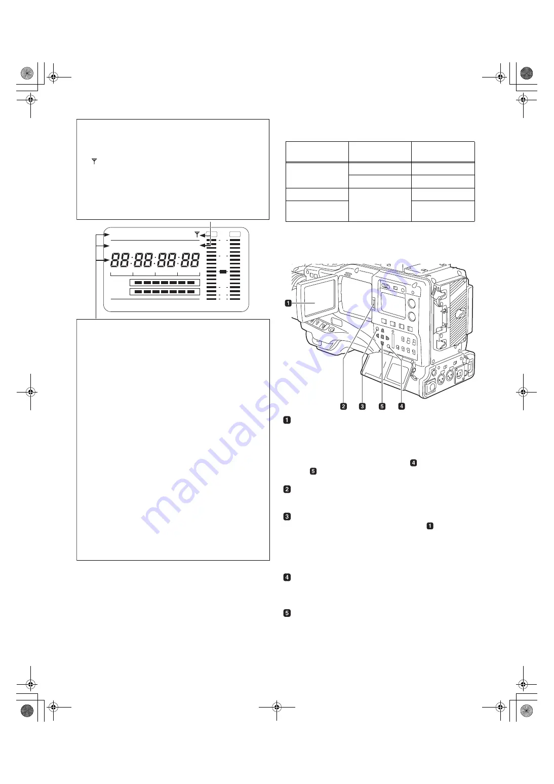
LCD Monitor
LCD monitor
The LCD monitor displays the video in the viewfinder.
Alternatively, it can show clips on the P2 card in a thumbnail
format.
In thumbnail display mode, clips can be edited or deleted, or
P2 cards can be formatted using the
MENU BAR button
and
CURSOR and SET buttons.
OPEN button
Used to open the LCD monitor.
THUMBNAIL button
This button switches the content on the
LCD monitor
from the video in the viewfinder to clip thumbnails. Another
press switches them back to the video from the viewfinder.
Note that this switchover is not performed during a recording
or playback.
MENU BAR button
In thumbnail display mode, this button allows you to
manipulate the menu bar (e.g., to delete clips).
CURSOR and SET buttons
The four triangular buttons are the CURSOR buttons, and
the center rectangular one is the SET button.
They are used to select a thumbnail and manipulate the
menu bar. For more information, see [Chapter 6
Manipulating Clips with Thumbnails].
Mode indication
W:
Stays illuminated in 16:9 mode.
DV:
Stays illuminated when the recording/playback format is DV.
GPS:
Stays illuminated when radio waves are not received during
GPS operation.
GPS
:
Stays illuminated when radio waves are received during GPS
operation.
P-REC:
Stays illuminated when PRE RECORDING is not set to 0
seconds, and blinks when recording is continued after the
recording tally lamp has gone out.
iREC:
Remains illuminated during INTERVAL REC mode recording,
and blinks during a pause.
i:
Blinks when INTERVAL REC mode is selected.
Time code indication
NDF:
Stays illuminated when the time code is in non-drop frame
mode.
DF:
Stays illuminated when the time code is in drop frame mode.
SLAVE:
Stays illuminated when the time code is externally locked.
HOLD:
Stays illuminated when the time code generator/reader value
is frozen.
CTL:
Stays illuminated when the DISPLAY switch is positioned at
[CTL] to display the CTL count.
TCG:
Stays illuminated when the DISPLAY switch is positioned at
[TC] (or [UB]) to display the TC (or UB) generator value.
TC:
Stays illuminated when the DISPLAY switch is positioned at
[TC] (or [UB]) to display the TC (or UB) reader value.
VTCG:
Stays illuminated when the DISPLAY switch is positioned at
[UB] to display the VIUB generator value.
VTC:
Stays illuminated when the DISPLAY switch is positioned at
[UB] to display the VIUB reader value.
TIME:
Stays illuminated when the DISPLAY switch is positioned at
[UB] to display the real-time hour, minute and second.
DATE:
Stays illuminated when the DISPLAY switch is positioned at
[UB] to display the real-time date.
No Indication:
The CTL, VTCG, TIME, and DATE stay off when the DISPLAY
switch is positioned at [UB] to display real time, time zone, hour and
minute.
Time count indication:
The time code, CTL, user bits and real time are shown.
<Note>
When the DISPLAY switch is positioned at UB, each press of the
HOLD button changes the indication through VTCG (VTC)
DATE
TIME
No Indication (Time Zone)
TCG (TC), in that order.
LOOP
h
MEDIA
E
F
Y
minM
s
frm
13
24
0
D
SLAVE HOLD W
GPS
BATT
E
F
OVER
OVER
10
OO
40
-dB
30
20
NDF
DV
DRIVE
OP-SLOT
VTCG TIME DATE P- REC
CTL
Position of DISPLAY
switch
Position of TCG
switch
Information Item
CTL
SET
Time code
F-RUN or R-RUN
CTL
TC
F-RUN/SET/
R-RUN
Time code
UB
User’s bit or real-
time, time zone
#,52:2'PINKUJDQQMࡍࠫ㧞㧜㧜㧡ᐕ㧟㧝ᣣޓἫᦐᣣޓඦᓟ㧢ᤨ㧠㧥ಽ


