background image

– 155 –

Chapter 8 Connecting to External Devices — Connection function via <USB2.0 DEVICE> or <USB3.0 HOST> terminal

Select [YES] in the confirmation message and press the control stick.

Exporting begins. A progress bar appears during exporting. (Fig. 1)
[COPY COMPLETED!] will be displayed when exporting is completed.

@

@

NOTE


t

For export with [TYPE S], P2 card data and copied data can be verified (compared) automatically after exporting. Verification at the time of export 
is enabled in the factory setting. When you set to disable verification at the time of export, exported data is not verified, and the time until export 
completes will shorten. To disable verification, set [VERIFY] to [OFF] in the main menu 

 [CLIP] 

 [STORAGE COPY SETUP]. For [FAT], verification 

is not performed regardless of this setting.


t

To discontinue the export process, press the control stick. A [CANCEL] confirmation message will appear. Select [YES] and press the control stick.


t

Even if you cancel the process during verification, copying to the P2 card will continue until it is completed.


t

microP2 memory cards that exceed 32 GB cannot be exported and imported. Use copied clips.

Copying to a storage device by clip

You can copy only the selected clips to a storage device.

Go to the thumbnail screen. Use the control stick to place the cursor on a clip you want to copy and press the control stick.

You can also select multiple clips.

Select [STORAGE] in the main menu 

 [CLIP] 

 [COPY] and press the control stick.

A list of folders or partitions in the storage device is displayed.

Select the copy destination and press the control stick.

Select [YES] in the confirmation message and press the control stick.

This starts the copying process. A progress bar is displayed during copying.
[COPY COMPLETED!] will be displayed when copying is completed.

@

@

NOTE


t

When the storage device has a [FAT] file system, the folders displayed are as follows:

Root

-  Folders down to the third level including the CONTENTS folder


t

To copy to a [TYPE S] storage device, one or more partitions are required. You can either format the storage device to [FAT] or perform copying after 
creating a partition through the export process.


t

To cancel the copy process, use the control stick to place the cursor on [CANCEL] and press the control stick. A [CANCEL] confirmation message will 
appear. Select [YES] and press the control stick. Clips copied halfway to the copy destination are deleted.

Storage device information display (explorer screen)

You can perform the following operations in the explorer screen display.


f

Storage device information display


f

Storage device partition or folder thumbnail display and selection


f

Target partition or folder selection

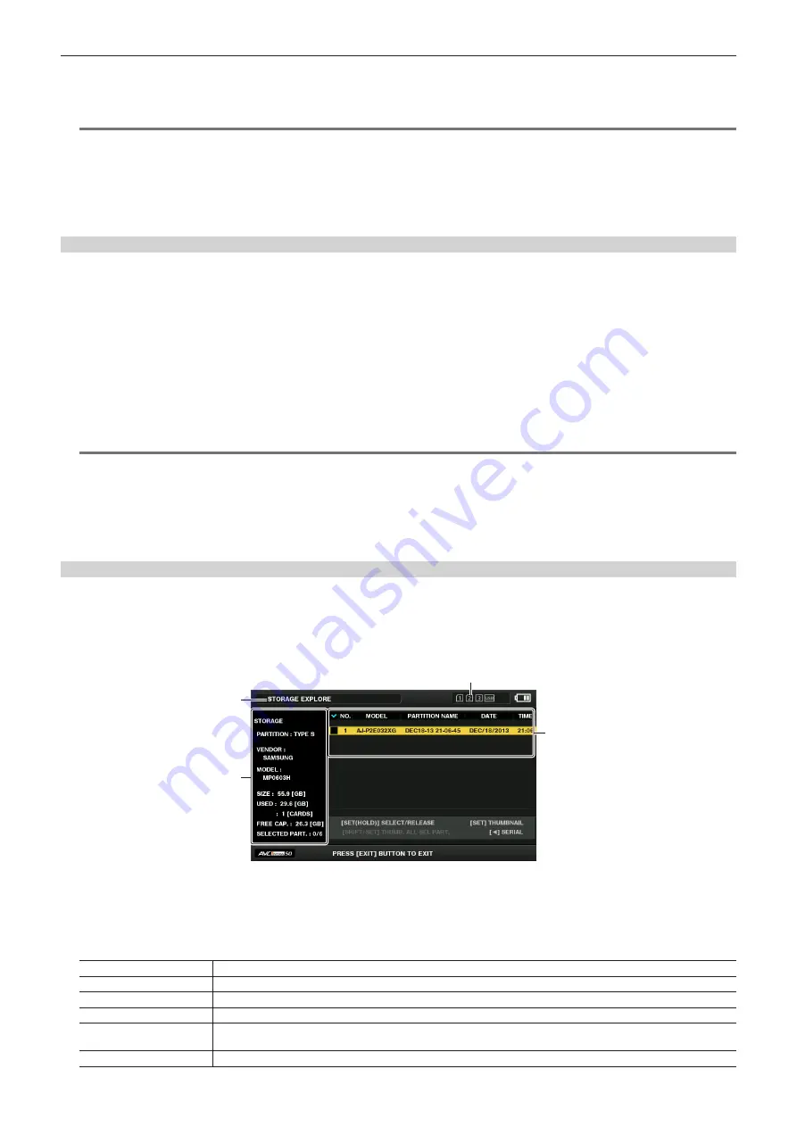
To display the explorer screen, select [STORAGE] in the main menu 

 [CLIP] 

 [EXPLORE] and press the control stick.

2

3

4

1

1  Storage device indicator

This displays the connected / not connected status and the storage device type.

2  Display mode

This indicates that the explorer screen of the storage device is currently displayed.

3  Device information

For [TYPE S] and [P2STORE] (storage devices that allow reading/writing by card)

[PARTITION]

[TYPE S]/[P2STORE]

[VENDOR]

Vendor name

[MODEL]

Model name

[SIZE]

Total capacity (unit: GB)

[USED]

Used capacity (unit: GB)

Used P2 card area (unit: number of clips), maximum of 23

[FREE CAP.]

Remaining capacity (unit: GB)

Содержание AJ-PX270EJ

Страница 1: ...is product please read the instructions carefully and save this manual for future use ENGLISH VQT5J85A E W0214HM0 YI Model No AJ PX270EJ Register now This product is eligible for the P2HD 5 Year Warranty Repair Program For details see page 5 http panasonic biz sav pass_e ...

Страница 2: ...ries only CAUTION Do not jar swing or shake the unit by its handle while the conversion lens or another accessory is attached Due to the added weight of the conversion lens any strong jolt to the handle may damage the unit or result in personal injury CAUTION In order to maintain adequate ventilation do not install or place this unit in a bookcase built in cabinet or any other confined space To pr...

Страница 3: ...f the plug contains a removable fuse cover you must ensure that it is refitted when the fuse is replaced If you lose the fuse cover the plug must not be used until a replacement cover is obtained A replacement fuse cover can be purchased from your local Panasonic Dealer How to replace the fuse 1 Open the fuse compartment with a screwdriver Or 2 Replace the fuse Fuse Fuse Or For Turkey EEE Yönetmel...

Страница 4: ...viewable 3 If the device is a Camera Recorder A professional camera recorder must be able to start quickly at any time but a Power Management function will cause an increase in the time taken to resume from Stand by mode It has been found that counterfeit battery packs which look very similar to the genuine product are made available to purchase in some markets Some of these battery packs are not ...

Страница 5: ...ranty http panasonic biz sav pass_e Free 5 years of Warranty Repairs Customers who register as users on the website will receive an extended warranty repair valid for up to five years P2HD 5 Year Warranty Repair Program 1 Thank you for purchasing this Panasonic P2HD device Register as a user for this device to receive a special service warranty up to five years of free warranty repairs Make sure t...

Страница 6: ... Video that was recorded by a consumer engaged in a personal and non commercial activity To play back AVC Video that was obtained from a video provider licensed to provide the video Visit the MPEG LA LLC website http www mpegla com for details f f Use of DCF Technologies under license from Multi Format Inc How to read this document r r Illustrations f f Illustrations of the camera menu screens and...

Страница 7: ...correction function 56 Black control function 56 Gamma function 56 Knee function 56 High color function 57 White clip function 57 Setting the electronic shutter 58 Shutter mode 58 Adjusting with the SEL PUSH SET dial button and MODE MENU CANCEL button 58 Flash band compensation FBC function 59 Setting the flash band compensation function 59 Variable frame rate VFR recording function 60 Native vari...

Страница 8: ...us display 141 Configuration of status display on screen 141 Selecting display items on screen 141 Displaying screen 141 Checking and displaying shooting status 145 Mode check display 146 Chapter 8 Connecting to External Devices 148 Connecting with headphones remote control or TV monitor 149 Headphones 149 Remote control 149 TV monitor 149 Connection function via USB2 0 DEVICE or USB3 0 HOST termi...

Страница 9: ...Before using the camera read this chapter For accessories refer to the leaflet supplied with the product Chapter 1 Overview ...

Страница 10: ...s for a long period of time r r After using the camera recorder either remove the battery or disconnect the AC cable from the power outlet r r Battery characteristics The battery is a rechargeable lithium ion battery It produces electrical energy via an internal chemical reaction This chemical reaction is easily influenced by the surrounding temperature and humidity so the effective usage time of ...

Страница 11: ...repare to record important images always shoot some advance test footage to verify that both pictures and sound are being recorded normally f f Should video or audio recording fail due to a malfunction of the camera or the P2 cards used we will not assume liability for such failure f f Set up or check the calendar and time zone before recording Setting the date time of the internal clock These set...

Страница 12: ...58 7 2 V 5800 mAh Product comparable to the included battery CGA D54 CGA D54s 7 2 V 5400 mAh Attaching and removing the battery page 26 SD memory card P2 memory card microP2 memory card Visit the support desk at the website P2 card page 33 For the latest information on P2 cards and SD memory cards that are not described in the Operating Instructions visit the support desk at the following website ...

Страница 13: ...r Schedule to support when future versions are upgraded Recording to the memory card P2 card The following can be recorded on the P2 card f f HD SD recording f f AVC Ultra system codec support f f Simultaneous recording microP2 memory card only f f Dual codec recording f f Variable frame rate Slow quick motion recording SD memory card Settings for user files and scene files etc can be stored in an...

Страница 14: ...hot mark or text memo f f Camera remote control collective operations of recording control and time code user bits In addition clip transferring can be performed by the FTP client function via the LAN terminal Contents which were recorded with AVC LongG 6 cannot be played back Connecting using wireless LAN connection and 4G adaptor Attaching the wireless module AJ WM30 optional to the USB2 0 HOST ...

Страница 15: ...This chapter describes the names functions and operations of parts on the camera Chapter 2 Description of Parts ...

Страница 16: ... the brightness of the screen according to the lighting conditions under which you are shooting 8 F AUDIO LEVEL dial page 63 In the following conditions the recording levels for the audio channels 1 to 4 can be adjusted f f When the CH1 CH2 switch is set to MANU f f When AUTO LEVEL CH3 AUTO LEVEL CH4 is set to OFF in the main menu AUDIO SETUP RECORDING CH SETTING Assignment of audio channels 1 to ...

Страница 17: ... speed changes depending on how strong the lever is pushed When pushed gently the speed becomes slower and when pushed strongly it becomes faster OFF The zoom lever does not work 22 ND FILTER switch page 46 Select the filter to suit the illumination of the subject 1 64 Reduce the amount of light entering the MOS sensor to 1 64 1 16 Reduce the amount of light entering the MOS sensor to 1 16 1 4 Red...

Страница 18: ...ort desk at the following website for the latest information not included in these operating instructions http pro av panasonic net SDHC memory cards are a standard that was established in 2006 by the SD Association for large capacity memory cards that exceed 2 GB SDXC memory cards are a standard that was established in 2009 by the SD Association for large capacity memory cards that exceed 32 GB 5...

Страница 19: ...trol the zoom operation and start stop operation of recording remotely 16 Tripod holes Attach the tripod bottom f f Mounting hole size 1 4 20 UNC screw length 5 5 mm or shorter 3 8 16 UNC screw length 5 5 mm or shorter 17 OPEN button page 161 Use this button when opening the cover of the USB2 0 HOST terminal at the bottom of the button 18 USB2 0 HOST terminal sub host page 161 This is the terminal...

Страница 20: ... 7 Viewfinder page 40 8 AUDIO INPUT 1 terminal XLR 3 pin page 30 Connect the audio equipment or the microphone 9 Rear tally lamp page 41 Light during shooting This lamp will blink when the battery level becomes low 10 Battery attachment page 26 11 Battery release button page 26 Remove the battery 12 microP2 memory card 1 access LED page 34 Indicate the access status of recording and playback of th...

Страница 21: ...r 2 Description of Parts Front side rear side 22 LAN terminal page 162 Connect the LAN cable 23 DC IN 12V terminal page 26 This is the input terminal for the external power supply Connect the supplied AC adaptor ...

Страница 22: ...er strap attachment page 28 Attach the shoulder strap 7 LCD monitor page 39 8 Zoom lever handle side page 53 Adjust the zoom of an image T Zoom in the image W Zoom out the image 9 Focal plane index Indicate the focal plane of the MOS sensor It provides a reference for measuring the accurate focal distance from the subject 10 Handle mounting holes Mount the handle f f Mounting hole size 1 4 20 UNC ...

Страница 23: ...orm operations of menus and area mode function 20 MENU button page 115 Press this button to display USER MENU Press this button for 3 seconds or more to display the main menu Press it while the thumbnail is displayed to display the operation screen of the thumbnail menu and clips can be deleted 21 SHIFT button page 101 Use this button together with the control stick or other buttons f f Press the ...

Страница 24: ...Before you use the camera mount the battery following the procedures in this chapter The mounting of accessories is also described in this chapter Chapter 3 Preparation ...

Страница 25: ... OUTPUT SEL VIDEO OUT is set to OFF With the cable not inserted into the HDMI OUT terminal t t The battery and camera recorder will become warm during use or while charging t t Make sure that batteries are discharged before storing them t t When stored for long periods of time it is recommended that you charge batteries once per year and then use up the battery capacity by using the battery in the...

Страница 26: ... Turn the power switch to OFF while holding down the lock release button Make sure that the LCD monitor has gone off 2 Lift up and remove the battery while holding down the battery release button Support the battery with your hand so that it does not fall down Using the AC adaptor Attaching 1 2 DC IN 12V terminal To the power outlet 1 Connect an AC cable Connect in the order shown in the figure ...

Страница 27: ...emove the AC adaptor from the DC IN 12V terminal NOTE t t When not using the camera remove the AC cable from the power outlet t t Use the supplied AC adaptor Do not use other AC adaptors t t The AC adaptor can be connected when attaching the battery to the camera When the AC adaptor is connected the camera will switch to be powered by the AC adaptor When removing the AC adaptor the camera will be ...

Страница 28: ... size of your hand 1 Open the cover and adjust the length of the strap 2 Replace the cover Attach the cover firmly Attaching the shoulder strap Attach the shoulder strap to the attachment lugs Longer than 20 mm Longer than 20 mm NOTE t t Make sure that the shoulder strap is securely attached Attaching the lens hood Removing 1 Rotate the lens hood counter clockwise ...

Страница 29: ...ns hood clockwise until it locks in with a click Opening and closing the lens cover Use the lens cover open close lever to open and close the lens cover Open the lens cover to take videos and photographs When not using the camera close the lens cover in order to protect the lens NOTE t t Do not press the lens cover with force Doing so may damage the lens and lens cover Attaching the eye cup Groove...

Страница 30: ... Connect the microphone connecting cable to the AUDIO INPUT 1 terminal on the camera Fig 3 4 Secure the microphone connecting cable with the microphone cable clamp 5 Set the INPUT 1 switch to match the microphone to be connected NOTE t t The microphone holder cannot be fixed with the screws originally attached on the camera Use the dedicated screws that came with the camera to fix the microphone h...

Страница 31: ...k release button Power switch How to turn on the power 1 Align the power switch to ON while holding down the lock release button The LCD monitor lights up How to turn off the power 1 Align the power switch to OFF while holding down the lock release button The LCD monitor goes off ...

Страница 32: ...02 30 02 00 Mid Atlantic 03 00 Moscow 02 30 03 30 Tehran 03 00 Buenos Aires 04 00 Abu Dhabi 03 30 Newfoundland 04 30 Kabul 04 00 Halifax 05 00 Islamabad 04 30 05 30 Bombay 05 00 New York 06 00 Dakar 05 30 06 30 Yangon 06 00 Chicago 07 00 Bangkok 06 30 07 30 07 00 Denver 08 00 Beijing 07 30 08 30 08 00 Los Angeles 09 00 Tokyo 08 30 09 30 Darwin 09 00 Alaska 10 00 Guam 09 30 Marquesas Islands 10 30 ...

Страница 33: ...ot number if a microP2 memory card is inserted later that microP2 memory card will be accessed later than the previously inserted microP2 memory cards f f Example When microP2 memory cards are inserted in two slots If microP2 memory cards are inserted into two slots the cards are used as P2 card in the order of the slot number 1 2 However if you remove the microP2 memory card from slot 1 and then ...

Страница 34: ...oes not light The P2 card starts to be recognized when playback ends t t Even if a P2 card is inserted in a vacant card slot during recording the P2 card may not be recognized immediately in the following instance Immediately after a pre recording Immediately after a recording slot is switched t t The P2 card access LED can be set to continuously off in the main menu OTHER FUNCTIONS ACCESS LED In ...

Страница 35: ...d to be updated depending on the type of P2 card page 180 t t Refer to our support desk at the following website for the latest information not included in these operating instructions http pro av panasonic net r r P2 card recording times Example when a 64 GB card is used System mode Recording format codec Recording time 1080P AVC Intra 100 Approx 32 min AVC LongG 25 Approx 128 min AVC LongG 12 Ap...

Страница 36: ...corded in the P2 format is in a file format they have excellent compatibility with computers The file structure is a unique format which in addition to video and audio data in MXF files contains various other important information items The folder structure links data recorded in the P2 format as shown below LASTCLIP TXT AUDIO AVCLIP CLIP ICON PROXY VIDEO VOICE CONTENTS Drive All these folders are...

Страница 37: ...e from the main menu SW MODE SUPER GAIN 1S EXP Enables disables the one second exposure function ATW Switches the auto tracking white balance functions to enabled disabled ATW LOCK Fixes the white balance value when pressing this item while the auto tracking white balance function is activated Resumes the auto tracking white balance function when pressing again SPOTLIGHT Switches the auto iris con...

Страница 38: ... REC MEDIA AUDIO MON SEL Assigns the function that switches between the display of the audio level meter and the audio channel CH1 CH2 and CH3 CH4 of output audio headphones built in speaker AUDIO OUT terminal and HDMI OUT terminal while the button is held down REC CHECK Assigns the recording check function USB MODE Assigns the function for switching the USB device mode or USB host mode to enabled...

Страница 39: ...e on a TV monitor The final check should be done on a TV monitor Adjusting the LCD monitor r r Adjusting the brightness contrast and color level Adjust LCD BRIGHTNESS brightness LCD CONTRAST contrast and LCD COLOR LEVEL color level in the main menu DISPLAY SETUP LCD SETTING These adjustments will not affect the images to be recorded r r Adjusting the backlight luminance Switches the brightness of ...

Страница 40: ... vertically to approximately 90 degrees 2 Adjust the characters inside the viewfinder screen so that they are clearly visible using the diopter adjustment lever NOTE t t The image brightness and color hue seen on the viewfinder and LCD monitor may be different from that seen on a TV monitor The final check of the color hue should be done on a TV monitor Adjusting the viewfinder r r Adjusting the b...

Страница 41: ...s exhausted four times per second f f The P2 card has less free space to record and the battery level is low one time per second f f The P2 card has been removed while being accessed four times per second f f The P2 card has no more space to record four times per second f f When the warnings such as the fluctuation of the reference signal for the GENLOCK IN VIDEO OUT terminal and a system error or...

Страница 42: ...This chapter describes the basic procedure for recording It also describes special shooting methods such as pre recording and loop recording Chapter 4 Shooting ...

Страница 43: ...vel 2 Select shooting mode with the AUTO MANUAL switch AUTO auto mode f f A is displayed at the upper part of the viewfinder and LCD monitor f f Focus iris gain shutter and white balance are automatically adjusted f f You can set the operation specifics for auto mode in the main menu AUTO SW MANUAL manual mode f f To adjust focus iris gain shutter speed and white balance manually set the camera to...

Страница 44: ... recording to two microP2 memory cards Selecting the resolution codec and video format for recording You can select the recording resolution 1080P 1080i 720P 480i 576i recording codec AVC Intra AVC LongG DVCPRO HD etc and the recording frame rate Set in the main menu SYSTEM MODE LINE FREQ and REC FORMAT r r Resolution 1920 1080 Setting Recording format LINE FREQ REC FORMAT CAMERA MODE 1080 59 94P ...

Страница 45: ...olution 720 576 Setting Recording format LINE FREQ REC FORMAT CAMERA MODE 576 50i DVCPRO50 50i DVCPRO 50i DV 50i 50i 576 50i 25P 576 25P over 50i 2 2 Pull Down NOTE t t In 480i 576i mode the video aspect ratio for recording and output can be changed ...

Страница 46: ...g in dark locations you can set super gain regardless of whether the camera is in auto mode or manual mode Select either 24dB 30dB 36dB or ALL in the main menu SW MODE SUPER GAIN You can switch to the selected gain by pressing a USER button assigned SUPER GAIN page 37 When ALL is selected each time the USER button is pressed the camera toggles 24dB 30dB 36dB normal gain settings in order NOTE t t ...

Страница 47: ...ith the focus ring the focus is automatically adjusted fine adjustment f f When the focus deviation is great it may not be in focus f f After executing auto adjustment it will not adjust automatically until you move the focus ring again Focus assist function The focus assist function enables you to focus the target easily Expanded display in the viewfinder and LCD monitor focus in red display disp...

Страница 48: ...ction and area focus bar function f f FOCUS Y GET Simultaneous operation of area focus function area brightness display and area focus bar function Operation of area mode function The function set in the main menu SW MODE AREA MODE can be used by performing the following operation when shooting or while in shooting standby 1 Press the control stick f f An area frame white is displayed 2 Press the ...

Страница 49: ...rection and up to 30 in the vertical direction 1 Select ON in the main menu DISPLAY SETUP LEVEL GAUGE NOTE t t The level gauge display is not recorded t t The level gauge is not displayed in the viewfinder t t The level gauge is not displayed when selecting MIRROR in the main menu DISPLAY SETUP SELF SHOOT t t While moving the camera the level gauge may not be displayed properly t t When shooting w...

Страница 50: ...ens aperture Adjust the iris so that the brightness of Y GET is approx 70 7 Press the AWB button White balance is automatically adjusted r r White pattern f f A white object cloth or wall near the subject may also be used for the white pattern f f Required size of white pattern is as follows 1 2 or more of the screen width 1 2 or more of the screen height f f Keep bright spotlights out of the scre...

Страница 51: ...unction that automatically tracks the white balance of images according to the lighting conditions The auto tracking white balance function can be assigned to each of A B and PRST of the WHITE BAL switch Configure the settings in the main menu SW MODE ATW Note that if the auto tracking white balance function is assigned to the USER button the function follows the operation of the USER button For d...

Страница 52: ... aperture is set to automatically shut out light t t During recording black balance cannot be adjusted t t During the automatic black balance execution recording to the P2 card is not performed by pressing the REC button t t The gain switching circuit is automatically switched during black balance adjustment Flicker or noise sometimes appears on the viewfinder screen and LCD monitor This is not a ...

Страница 53: ...he zoom at high speed NOTE t t To operate the zoom with higher speed press the USER button where FAST ZOOM is assigned in the main menu USER SW to enable disable FAST ZOOM t t When FAST ZOOM is enabled the motorized zoom can operated with higher speed when the zoom lever is pushed to the end However the zoom sound becomes louder than usual If the sound of the motorized zoom is obtrusive disable FA...

Страница 54: ...n skin look smoother in images R Y 0 255 255 R Mg B G Cy Yl B Y 0 Q axis I axis Fig 1 I CENTER Q WIDTH Q PHASE I WIDTH r r General settings SKIN TONE DTL A SKIN TONE DTL B SKIN TONE DTL C Selects what kind of skin color where the skin tone detail function should work from the three data SKIN TONE DTL A SKIN TONE DTL B SKIN TONE DTL C SKIN TONE DTL A SKIN TONE DTL B SKIN TONE DTL C can be set alone...

Страница 55: ...tic white balance is performed AWB B GAIN OFFSET Sets whether to keep the values set for R GAIN AWB B and B GAIN AWB B or reset them Chroma setting function This function sets color saturation and phase It applies effects on whole images It cannot be set to individual color hue r r General settings CHROMA LEVEL Sets the chroma level of the PR signal and PB signal When the vector scope is used the ...

Страница 56: ...nd makes it less dark r r Advanced settings Configure the settings in the main menu SCENE FILE RGB BLACK CONTROL SETTING R PED Sets the pedestal level of Rch G PED Sets the pedestal level of Gch B PED Sets the pedestal level of Bch PEDESTAL OFFSET Sets whether to keep the values set for each item of R PED G PED and B PED or reset them when automatic black balance adjustment is performed Gamma func...

Страница 57: ...s function sets the color dynamic range r r General settings HI COLOR SW Turns the mode that expands the color dynamic range ON OFF HI COLOR LVL Selects the level of mode that expands the color dynamic range r r Advanced settings Use the camera in a general settings White clip function This function sets the brightest part of video signals to be not brighter than a certain level r r General settin...

Страница 58: ... in the main menu SCENE FILE VFR f f White balance variable mode can be selected only when VAR is set in the main menu SW MODE W BAL PRESET and the WHITE BAL switch is set to the PRST position 3 Press the SEL PUSH SET dial button and select shutter mode or synchro shutter mode Each time the button is pressed the normal shutter mode and synchro shutter mode will be toggled 4 Turn the SEL PUSH SET d...

Страница 59: ... strobe lights Horizontal lines appear in the video when the flash strobe lights Using the flash band compensation function The flash band compensation function is activated when there are large changes in brightness at the bottom of the screen regardless of whether there is flash strobe light The flash band compensation function may be activated depending on the shooting environment such as where...

Страница 60: ...fps 25fps 26fps 27fps 28fps 30fps 32fps 34fps 37fps 42fps 45fps 48fps 50fps Effect on playback Quick motion Quicker in smaller value Standard Slow motion Slower in smaller value Audio recording Not available Available Not available NOTE t t During native variable frame rate recording pre recording loop recording interval recording one shot recording dual codec recording and one clip recording can ...

Страница 61: ...p recording interval recording one shot recording dual codec recording and one clip recording can not be performed t t Audio can be recorded t t Auto iris auto focus and auto tracking white balance do not function when the frame rate is set to 9fps or lower or when the shutter speed is set to lower than 1 12 They must be operated manually ...

Страница 62: ...an select 24BIT and 16BIT You can select the main menu SYSTEM MODE AUDIO SMPL RES AVC G50 AVC G25 24BIT fixed AVC G12 DVCPRO HD DVCPRO50 DVCPRO DV 16BIT fixed Using the built in microphone 1 Set the CH1 SELECT switch to the INT L position The L audio signal of the built in microphone is recorded on audio channel 1 2 Set the CH2 SELECT switch to the INT R position The R audio signal of the built in...

Страница 63: ...n In this case adjust the recording level manually Manual adjustment r r Setting audio channels 1 2 1 Set the CH1 CH2 switch to MANU 2 Set in the main menu AUDIO SETUP OUTPUT SETTING AUDIO OUT to CH1 CH2 so that the audio level meter display shows CH1 and CH2 Make sure that the audio level meter display is CH1 and CH2 3 Adjust with the AUDIO LEVEL CH1 AUDIO LEVEL CH2 dial If the audio meter indica...

Страница 64: ...tion is indicated by bars in four levels f f If HOLD is set in the main menu OTHER FUNCTIONS P OFF GPS DATA the GPS position information can be retained f f Longitude latitude and date time can be viewed in the mode check NOTE t t If it cannot position even after waiting several minutes it means that the GPS signals are weak and difficult to receive t t Position in the open space with a clear view...

Страница 65: ...t Video and audio according to the preset time sometimes cannot be recorded in the following cases Immediately after the power is turned on After recording related settings have been altered in the setting menu Immediately after the P2 card is inserted After playback or recording check is performed t t The pre recording function does not function in the following cases When an item other than NORM...

Страница 66: ...ded content Content recorded Start recording 1 Check the settings of each item in the main menu SYSTEM MODE For details on system modes in which the loop recording function can be used refer to the table in System modes and recording functions page 73 For details on menu operations refer to Setting menu basic operations page 115 2 Set LOOP in the main menu RECORDING SETUP RECORDING 3 Press the REC...

Страница 67: ... automatically add a text memo to the recording start point set ON in the main menu RECORDING SETUP START TEXT MEMO To view or play back the point of the added text memo select TEXT MEMO CLIPS in the main menu CLIP REPOSITION and place the cursor on the target clip For details refer to Playing back from the text memo position page 103 To cue up the text memo position when playing back set CLIP TEX...

Страница 68: ...roP2 memory card in slot 2 the slot with remaining memory space For details on system modes in which simultaneous recording can be used refer to the table in System modes and recording functions page 73 NOTE t t Start recording when two microP2 memory cards are recognized When recording is started before both microP2 memory cards are recognized normal recording is performed using either microP2 me...

Страница 69: ...not be added during loop recording interval recording or one shot recording If an operation is invalid SHOT MARK INVALID is displayed when the button is pressed t t During playback setting or canceling the shot mark is not available While pausing the playback setting or canceling the shot mark is available t t The following restrictions apply when adding shot marks to combined clips such as those ...

Страница 70: ...UP Item Description of settings ZEBRA1 DETECT Sets the extraction level of zebra pattern 1 0 109 f f Factory setting 70 ZEBRA2 DETECT Sets the extraction level of zebra pattern 2 0 109 f f Factory setting 85 ZEBRA2 Sets on off of zebra pattern 2 and selects the type ON SPOT OFF f f Factory setting SPOT SPOT The image level from the setting value of ZEBRA1 DETECT to the setting value of ZEBRA2 DETE...

Страница 71: ... LCD monitor When using a tripod disabling the image stabilizer function will allow you to obtain natural images NOTE t t When there is a lot of shaking while shooting and when following a moving subject the function may not be able to stabilize the image Dynamic range stretcher function You can increase the dynamic range by compressing the image signal for the extremely bright areas that are over...

Страница 72: ...LCD monitor The viewfinder does not show the waveform f f The waveform is not displayed while the focus assist function EXPAND is active f f The waveform display cannot be recorded Direct menu operation This function changes the settings of values for shutter speed synchro scan shutter speed white balance and frame rate that are displayed on the screen using the MODE MENU CANCEL button f f Variabl...

Страница 73: ...aspect ratio for recording and output NOTE t t When LINE FREQ or REC FORMAT is changed video or audio may be interrupted This is not a malfunction System modes and recording functions The following shows the relationship between system modes and recording functions on this camera f f l are supported and are not supported System mode Recording function LINE FREQ REC FORMAT CAMERA MODE AUDIO SMPL RE...

Страница 74: ... 50P AVC I100 50P 24BIT 16BIT l l l AVC I100 25PN AVC G25 50P 24BIT l AVC G12 50P 16BIT l 1080 59 94i AVC I100 60i 24BIT 16BIT l l l AVC I50 60i l l l AVC G50 60i 24BIT l AVC G25 60i l AVC G12 60i 16BIT l DVCPRO HD 60i 60i l l l 1080 50i AVC I100 50i 24BIT 16BIT l l l AVC I50 50i l l l AVC G50 50i 24BIT l AVC G25 50i l AVC G12 50i 16BIT l DVCPRO HD 50i 50i l l l 720 59 94P AVC I100 60P 24BIT 16BIT...

Страница 75: ...4i DVCPRO50 60i 60i 16BIT l 30P l DVCPRO 60i 60i l 30P l DV 60i 60i l 30P l 576 50i DVCPRO50 50i 50i 16BIT l 25P l DVCPRO 50i 50i l 25P l DV 50i 50i l 25P l 1 AVC G6 2CH MOV 2 SHQ 2CH MOV HQ 2CH MOV LOW 2CH MOV List of recording settings and recording functions The recording modes of the camera act as follows depending on the setting of RECORDING in the main menu RECORDING SETUP Even in Available ...

Страница 76: ...ut signals from the SDI OUT terminal and HDMI OUT terminal 3G SDI OUT Selects the 3G HD SDI signal type output from the SDI OUT terminal from LEVEL A and LEVEL B at 1080P DOWNCON MODE Selects the mode of the down converter output signal mode from the SDI OUT or GENLOCK IN VIDEO OUT terminal in HD mode 1080P 1080i or 720P Selecting video output from each terminal f f indicates an item that cannot b...

Страница 77: ...80 50P 4ch AVC I100 25PN 1080 25PN Native 1080 25P over 50P 2 2 4ch AVC I100 50P Disabled ON 1fps 50fps 1080 50P VFR 1080 50P VFR 4ch AVC I100 25PN 1080 25PN Native VFR 5 1080 50P VFR No audio 6 1080 50i AVC I100 50i AVC I50 50i AVC G50 50i AVC G25 50i AVC G12 50i Disabled Disabled Disabled 1080 50i 1080 50i 4ch DVCPRO HD 50i 50i 1080 50i 1080 50i 4ch 720 59 94P AVC I100 60P AVC I50 60P AVC G50 60...

Страница 78: ...t SPLIT in the main menu RECORDING SETUP FILE SPLIT Checking the setting status Push the DISP MODE CHK switch on the camera towards the CHK side twice to check the menu values of REC MEDIA and PROXY MODE with the mode check function Recording modes and recording signals video audio The following settings are available only when 1080 59 94i or 1080 50i is set in the main menu SYSTEM MODE LINE FREQ ...

Страница 79: ... data recordings page 80 t t Data deleted as a result of formatting cannot be restored Always check the data before formatting Formatting SD memory cards 1 Insert the SD memory card into the camera 2 Select YES in the main menu CARD FUNCTIONS FORMAT SD CARD This completes formatting the SD memory card Proxy data recording time approximate Recording mode Total recording rate Recording time per 1 GB...

Страница 80: ...d in the internal proxy module PROXY ERROR f f A proxy data recording error occurred PROXY REC WARNING f f If a proxy data recording error occurs the proxy data currently being recorded will be processed as below The proxy data being recorded to the P2 card will be deleted The proxy data being recorded to the SD memory card will not be restored The proxy data will not be properly recorded Turn off...

Страница 81: ...rd Copying proxy data to the SD memory card 1 Press the THUMBNAIL button to display the thumbnail screen 2 Use the control stick to move the cursor to the clip to be copied and press the control stick 3 Select SD CARD in the main menu CLIP COPY 4 Select YES in the confirmation message and press the control stick NOTE t t If SD END is displayed and the proxy data being recorded to the SD memory car...

Страница 82: ...mory card Scene file 1 F2 F3 F4 F5 F6 F1 Scene file 8 F2 F3 F4 F5 F6 1 Select INITIALIZE in the main menu SCENE FILE LOAD SAVE INITIALIZE By scene file unit as selected in the main menu SCENE FILE FILE SELECT 2 Select LOAD or SAVE in the main menu SCENE FILE LOAD SAVE INITIALIZE By scene file unit as selected in the main menu SCENE FILE FILE SELECT 3 Select LOAD or SAVE in the main menu CARD FUNCT...

Страница 83: ...mera and then release This releases the SD memory card from the card slot Remove the SD memory card and close the slot cover Note the following points when using or storing memory cards f f Avoid high temperature and humidity f f Avoid water droplets f f Avoid charging with electricity Store the SD memory card with the card still inserted into the camera and with the slot cover closed Performing o...

Страница 84: ...ick or the SEL PUSH SET dial button Loading written user data 1 Select LOAD in the main menu OTHER FUNCTIONS USER FILE and press the control stick or SEL PUSH SET dial button The confirmation screen is displayed If SYSTEM RESTART is displayed on the confirmation screen the camera will restart after reading out is complete 2 Select YES and press the control stick or SEL PUSH SET dial button Loading...

Страница 85: ...PUSH SET dial button The selected scene file is loaded from the camera Restoring the scene file setting data to the factory settings 1 Select the file to be restored to the factory settings in the main menu SCENE FILE FILE SELECT and press the control stick or SEL PUSH SET dial button 2 Select INITIALIZE in the main menu SCENE FILE LOAD SAVE INITIALIZE and press the control stick or SEL PUSH SET d...

Страница 86: ...card the current setting values are overwritten as well as the data saved in the camera f f All scene files F1 to F6 are overwritten Saving scene files Fig 1 Fig 2 1 Select SAVE in the main menu CARD FUNCTIONS SCENE FILE Fig 1 2 Select a file number 1 to 8 and press the control stick or SEL PUSH SET dial button Fig 2 The title entry screen and keyboard are displayed 3 Enter desired characters on t...

Страница 87: ...t signal GL PHASE 1080i 1080P HD Y HD SDI HD SDI output matches the HD Y input signal Down converter output has a delay of approx 90 H from the HD Y input signal COMPOSITE Down converter output matches the HD Y input signal HD SDI output has an advance of approx 90 H from the HD Y input signal Composite HD SDI HD SDI output matches the composite input signal Down converter output has a delay of ap...

Страница 88: ...amera frame rate information The LTC UB value of the recording start time can be recorded on the user bits of the clip metadata r r Date time real time f f By means of the internal clock year month day and time can be displayed on the viewfinder LCD monitor and on the output image of the GENLOCK IN VIDEO OUT terminal etc f f The internal clock is used for measuring the free run time code while the...

Страница 89: ...E TC OUT LTC VITC of HD SDI 1080 59 94P AVC I100 60P AVC G25 60P AVC G12 60P LTC is output LTC is output AVC I100 30PN 30fps LTC is output LTC is output Other than 30fps Matches to the recording TC at the top of recording 30 frames second Matches to the recording TC at the top of recording 30 frames second AVC I100 24PN 24fps LTC is converted to 30 frames and output LTC is output Other than 24fps ...

Страница 90: ...80 59 94i AVC I100 60i AVC I50 60i AVC G50 60i AVC G25 60i AVC G12 60i Follows UBG MODE Follows VITC UBG MODE DVCPRO HD 60i 60i 1080 50P AVC I100 50P AVC G25 50P AVC G12 50P Follows UBG MODE Follows VITC UBG MODE AVC I100 25PN 25fps Frame information lock Other than 25fps 1080 50i AVC I100 50i AVC I50 50i AVC G50 50i AVC G25 50i AVC G12 50i Follows UBG MODE Follows VITC UBG MODE DVCPRO HD 50i 50i ...

Страница 91: ...ser bits settings Sets the user bits to be recorded in the sub code area in the main menu RECORDING SETUP UBG MODE Item Description USER Records internal user values You can set the user value in the main menu RECORDING SETUP UB PRESET Setting values are held even when the power is turned off For details refer to How to input user bits page 92 TIME Records the time measured by the internal clock D...

Страница 92: ... Frame rate information recorded on user bits Saving the frame rate values for the image information shot saved according to the frame rate set in the main menu SYSTEM MODE to user bits allows you to use the editor personal computer editing software Information is always saved in VITC UB In addition selecting FRAME RATE in the main menu RECORDING SETUP UBG MODE saves the information in user bits L...

Страница 93: ...ary NOTE t t When the power switch has been switched to ON OFF ON the backup accuracy of the time code in the free run mode is approximately 2 frames Time codes in variable frame rate f f In 24PN recording is 24 frames output is 30 frames which matches 2 3 pull down images f f The advance rate of the recording and output time code matches real time only when the image frame rate is 24P When 60P re...

Страница 94: ...nerator lock is disrupted recording cannot be performed normally TEMPORARY PAUSE IRREGULAR SIG is displayed in the viewfinder screen and the clip is divided The continuity of the time code is not guaranteed Recording resumes when the signal returns to normal However during loop recording recording does not resume f f When the time code is externally locked the time code is instantaneously locked t...

Страница 95: ... supplied video output 3 Set TCG TCR in the main menu OUTPUT SEL TC OUT NOTE t t If you set TC OUTPUT REF to VIDEO OUT in the main menu OUTPUT SEL the input time code will be output to match the video output delay Connecting and setting the genlock and time code input output The relationship of the connecting and settings between the genlock and time code input output is shown in the table When th...

Страница 96: ...k You can set either of two types in the main menu DISPLAY SETUP REC COUNTER TOTAL The camera will continuously count until reset using the RESET button Even if you replace the P2 card or turn off the power the value will be maintained CLIP Each time you start recording the counter value will clear and the count will start from 0 You can shoot always while checking the recording time of the clip y...

Страница 97: ...ata including additional information such as images audio text memo and metadata that are created from one shooting are saved as a clip You can play back and edit clips with the camera Chapter 5 Playback ...

Страница 98: ...se the playback at the beginning of the previous clip During a pause press the button to pause the playback at the beginning of the next clip During a pause press of the AUDIO MON ADV button to advance a frame and press to return one frame f f Pressing the button during clip playback stops the playback and returns the display to the thumbnail screen NOTE t t When playing clips it is not necessary ...

Страница 99: ...nd network connection are displayed as follows White The card slot number in which the P2 card is inserted is displayed in white Yellow The card slot number of the P2 card in which the clip in the cursor position is saved is displayed in yellow If the clips are recorded across multiple P2 cards all slot numbers of those cards that contain the clips are displayed NOTE The frame turns red if the ins...

Страница 100: ...lays the clip length duration at the cursor position and the current rough playback position against the clip length Playback position display is enabled when RESUME is selected in the main menu CLIP THUMBNAIL SETUP PB POSITION The approximate playback position is displayed when the playback start position is not at the beginning 10 Number of selected clips Shows the number of selected clips and t...

Страница 101: ...ected clips displayed on the lower right corner of the screen changes according to the selection Deselecting clips 1 Move the cursor to the selected clip and press the control stick This deselects the clip NOTE t t While holding down the SHIFT button press the EXIT button to deselect all the clips at once Setting thumbnail screen display You can customize the thumbnail screen according to usage Se...

Страница 102: ...NAIL SIZE t t A maximum of six items can be displayed at the same time t t When six items are already selected all unchecked items cannot be selected You can change your item selection by unchecking selected items Changing thumbnails Replace thumbnails with images that include previously attached text memos while images are recorded or played back Fig 1 Fig 2 1 Add text memos to images to be chang...

Страница 103: ... shot mark to or deleting the shot mark from a clip recorded across multiple P2 cards do this with all these P2 cards inserted into card slots Text memo You can add text memos during recording or playback Text memos can be used to play clips at some point or break clips into chunks and copy the necessary portions Adding the text memo You must assign TEXT MEMO to the USER button USER1 to USER8 befo...

Страница 104: ...ect the desired text memo in a clip 2 Move the cursor over the text memo to be copied and press the control stick You can select multiple text memos 3 Select COPY in the main menu CLIP 4 Select the copy target slot using the control stick and select YES f f Copying starts f f The portion between the selected text memo and the next one is copied If no text memo is found after the selected one then ...

Страница 105: ...is not performed when the following error messages are displayed LACK OF CAPACITY Copying could not be performed because the recording capacity of the copy destination is insufficient UNKNOWN CONTENTS FORMAT Copying could not be performed because a defective clip is selected NO COPY TO SAME CARD Copying could not be performed because you are attempting to copy to the same card TOO MANY CLIPS Copyi...

Страница 106: ... THUMBNAIL Displays the location of the frame frame offset and the size height and width of the image selected as the thumbnail image PROXY Displays information such as proxy format when proxy is added 1 You can select the USER CLIP NAME recording method For details refer to Selecting the USER CLIP NAME recording method page 107 2 When entering MEMO make sure to enter TEXT It is not possible to re...

Страница 107: ...s been loaded or when setting disables recording of loaded clip metadata Same as CLIP NAME The COUNT value is indicated as a four digit number The COUNT value is incremented each time a new clip is generated if the clip metadata has been loaded and TYPE2 has been selected as the recording method The COUNT value can be reset using the following method When you select PROPERTY in the main menu RECOR...

Страница 108: ...n menu CLIP PROPERTY 2 3 1 4 5 1 Clip information Displays the indicators added to the clip and the number of added text memos The mark will be displayed if the P2 card in which the clip is recorded is write protected 2 Clip number NOTE t t For clips that cannot be played back the number is displayed in red 3 Thumbnail 4 Clip information Displays detailed information about the clip CLIP NAME Displ...

Страница 109: ...N shooting location data of SHOOT the item cannot be deleted alone By setting the ALTITUDE item to empty other LONGITUDE and LATITUDE items are collectively deleted t t Metadata of clips with incomplete clip indicator cannot be repaired Repair of metadata of clips recorded across multiple P2 cards must be performed after inserting all of the P2 cards t t Any MEMO with 101 characters or more cannot...

Страница 110: ... NG CARD Indicates that the card is a microP2 memory card which cannot authenticate a CPS password Use the control stick to place the cursor on the P2 card where data to be accessed is saved and press the control stick to display detailed information on the P2 card Specific information such as the serial number and the user ID can be checked Fig 1 When the maximum number of clips that can be recor...

Страница 111: ...IP PROPERTY CPS PASSWORD The software keyboard to enter the CPS password is displayed 2 Enter the CPS password with the keyboard Enter PASSWORD and RETRY PASSWORD for verification and select OK to set the CPS password f f When entry of the CPS password has succeeded the message SETTING PASSWORD COMPLETED is displayed f f When entry of the CPS password has failed the warning message is displayed Fo...

Страница 112: ...d or format the card and use it as recording media or remove it from the camera Do not perform any operation other than manual authentication and formatting with the failed card inserted SD memory card status display The status display enables confirmation of the SD memory card format condition available memory space etc Select SD CARD in the main menu CLIP PROPERTY The same information can be dis...

Страница 113: ...This chapter describes how to operate the camera menus the structure and details of the setting menu Chapter 6 Menu Operations ...

Страница 114: ... the settings for the auto mode Auto iris auto gain control auto tracking white balance and auto focus functions can be set separately This menu item cannot be set when the thumbnail screen is displayed RECORDING SETUP Configures various settings when performing recording and playback Set the system frequency the number of lines recording format and recording method CLIP Used when performing vario...

Страница 115: ...n menu operations Main menu operation is the same as the other menus except when opening the menu screen b a c d e f g a EXIT button b Control stick c MENU button Operation panel of the LCD monitor d SHIFT button e SEL PUSH SET dial button f MENU button g MODE MENU CANCEL button Fig 1 Fig 2 Fig 3 Fig 4 r r Selecting menu item using control stick 1 Press and hold the MENU button for three seconds o...

Страница 116: ...USH SET dial button f f The confirmation screen is displayed depending on the menu item Turn the SEL PUSH SET dial button to select the operation and then press the SEL PUSH SET dial button A checkmark is placed in front of the set item f f In some menus a screen for value setting is displayed Fig 3 4 Press the MENU button to close the menu f f This brings you back automatically to the previous sc...

Страница 117: ... 117 Chapter 6 Menu Operations Setting menu display Initializing user file and all scene files simultaneously 1 Select the main menu OTHER FUNCTIONS MENU INITIALIZE 2 Select YES ...

Страница 118: ...ODE 50 Hz SYNC SCAN TYPE Switches the synchro scan display settings sec Displays in time deg Displays at shutter open angle f f Factory setting sec SYNCHRO SCAN Displays the speed of the synchro scan shutter that is used when shooting video for television etc When SYNC SCAN TYPE sec and SYSTEM MODE 59 94 Hz f f 60i 60p 1 60 0 1 249 8 f f 30P 1 30 0 1 249 8 f f 24P 1 24 0 1 249 8 When SYNC SCAN TYP...

Страница 119: ...lly obtained The obtained data becomes the table data of A B or C selected in DETECT TABLE Multiple color information for A B and C cannot be obtained simultaneously SKIN DTL EFFECT Sets the effective level of the skin tone detail 0 31 f f Factory setting 16 I CENTER Sets the center position of the upper I axis setting the area that displays the skin tone 0 255 f f Factory setting 35 I WIDTH Sets ...

Страница 120: ...working or when it is preset Also in automatic white balance operation the color can be changed on the Rch axis by changing the output of Rch 400 400 f f Factory setting 0 B Gain Displays the Bch output when the WHITE BAL switch is at the B position and automatic white balance is working or when it is preset Also in automatic white balance operation the color can be changed on the Bch axis by chan...

Страница 121: ...rects the color saturation between blue and cyan 63 63 f f Factory setting 0 B Cy PHASE Corrects the hue between blue and cyan 63 63 f f Factory setting 0 Cy SAT Corrects cyan color saturation 63 63 f f Factory setting 0 Cy PHASE Corrects the cyan hue 63 63 f f Factory setting 0 Cy G SAT Corrects the color saturation between cyan and green 63 63 f f Factory setting 0 Cy G PHASE Corrects the hue be...

Страница 122: ...ILMLIKE2 FILM REC The cine gamma feature for film VIDEO REC The cine gamma feature for video f f Factory setting HD GAMMA SETTING MASTER GAMMA Sets the master gamma in 0 01 steps 0 30 0 75 f f Factory setting 0 45 F REC DYNAMIC LVL When FILM REC is selected in GAMMA MODE SEL dynamic range is set If an item other than FILM REC is selected no settings are changed 200 300 400 500 600 f f Factory sett...

Страница 123: ...s switches ON OFF using the USER button operations A IRIS LEVEL EFFECT Adjusts the brightness in the auto iris mode Increase the value to brighten and decrease the value to darken the convergence of auto iris 50 50 f f Factory setting 0 SYSTEM MODE Configure the settings regarding the recording format of video and audio Item Description of settings LINE FREQ Sets the signal format of the camera If...

Страница 124: ...utton INHIBIT SCENE FILE SEL LEVEL GAUGE RESET WFM D ZOOM DRS FBC S GAIN 1S EXP ATW ATW LOCK SPOTLIGHT BACKLIGHT BLACKFADE WHITEFADE A IRIS LEVEL IRIS Y GET FOCUS ASSIST FOCUS MACRO OIS FAST ZOOM ZEBRA EVF ON OFF PRE REC TEXT MEMO SHOT MARK DEL LAST CLIP SLOT SEL REC MEDIA AUDIO MON SEL REC CHECK USB MODE f f Factory setting ZEBRA USER5 Sets the function to be assigned to the WFM button INHIBIT SC...

Страница 125: ...0 W BAL PRESET Sets the color temperature to be assigned to the PRST position of the WHITE BAL switch 3200K 5600K VAR f f Factory setting 3200K W BAL VAR Sets the value of VAR in W BAL PRESET It can also be operated by the SEL PUSH SET dial button Enabled when W BAL PRESET is set to VAR and the WHITE BAL switch is at PRST 2000K 15000K f f Factory setting 3200K H ZOOM SPEED Sets the zoom speed when...

Страница 126: ...for SNG Satellite News Gathering ARIB Uses ARIB standard color bars f f Factory setting SMPTE FRONT REC Sets operation of the REC button on the front of the camera INHIBIT Does not activate the operation ACTIVE Activates the operation f f Factory setting ACTIVE AUTO SW Configure the settings regarding the auto mode Auto iris auto gain control auto tracking white balance and auto focus functions ca...

Страница 127: ...RECORDING HOLD Selects whether to hold RECORDING settings ON Holds the settings OFF Does not hold the settings It will always be NORMAL the next time when the power is turned on f f Factory setting OFF ONE SHOT TIME Sets the recording duration of one shot recording 1frm 2frm 4frm 8frm 16frm 1s f f Factory setting 1frm INTERVAL TIME Sets the interval duration for interval recording 2frm 4frm 8frm 1...

Страница 128: ...o the card and continuously records that value f f Factory setting USER EXT REC META DATA LOAD Loads the metadata upload file saved to the SD memory card RECORD Sets whether to add loaded metadata at a recording ON Adds metadata OFF Does not add metadata f f Factory setting OFF USER CLIP NAME Sets data to be recorded to USER CLIP NAME When RECORD is ON TYPE1 Records setting values of the loaded da...

Страница 129: ...network connection STORAGE Switches to the information display screen for storage device FTP Switches to the information display screen for FTP server AUTHENTICATE When this menu is selected from the card status screen a software keyboard is displayed to enter the CPS password If the password is entered and OK is selected the CPS password is set to the camera When the set CPS password is successfu...

Страница 130: ...plays the videographer PLACE NAME Displays the shooting location PROGRAM NAME Displays the program name SCENE NO Displays the scene number TAKE NO Displays the take number REPORTER Displays the reporter PURPOSE Displays the purpose of shooting OBJECT Displays the object of shooting START UB Displays the start user bits REC RATE Displays the recording frame rate LAST UPDATE Displays the date of las...

Страница 131: ...audio channel 4 is OFF 0 100 f f Factory setting 70 MIC LOWCUT CH1 Enables disables the lowcut filter for audio channel 1 ON OFF f f Factory setting OFF MIC LOWCUT CH2 Enables disables the lowcut filter for audio channel 2 ON OFF f f Factory setting OFF MIC LOWCUT CH3 Enables disables the lowcut filter for audio channel 3 ON OFF f f Factory setting OFF MIC LOWCUT CH4 Enables disables the lowcut fi...

Страница 132: ... signal ON OFF ON OFF The down converter output signal contains detail components set during HD signal processing This setting superimposes the detail components exclusive to down converter output to that signal f f Factory setting ON H DTL LEVEL Sets horizontal detail correction level for the down converter output signal 0 31 f f Factory setting 8 V DTL LEVEL Sets vertical detail correction level...

Страница 133: ...terminal on the camera Cannot be changed DHCP Sets whether to use automatic acquisition via DHCP Mutually exclusive with DHCP SERVER setting ENABLE Uses automatic acquisition DISABLE Does not use automatic acquisition Set IP ADDRESS SUBNET MASK DEFAULT GATEWAY PRIMARY DNS and SECONDARY DNS f f Factory setting ENABLE IP ADDRESS Sets the IP address when DISABLE is selected in DHCP f f Factory settin...

Страница 134: ...AY Displays the network status INITIALIZE Restores the network setting status to the factory settings PING Checks network connection using PING commands DISPLAY SETUP Configure the settings regarding the details to be displayed on the viewfinder or LCD monitor These menu items cannot be set when the thumbnail screen is displayed Item Description of settings MENU DISPLAY Selects the LCD monitor or ...

Страница 135: ...FF ON OFF f f Factory setting ON OTHER DISPLAY Sets display details of other information PARTIAL Displays information partly ALL Displays all information USER Displays the information set in DISPLAY SETTING f f Factory setting PARTIAL DISPLAY SETTING IRIS Displays hides F value and auto iris control status ON OFF f f Factory setting ON GAIN Displays hides gain value ON OFF f f Factory setting ON S...

Страница 136: ...aking level of the viewfinder and LCD monitor 7 7 f f Factory setting 0 EVF PEAK FREQ Adjusts the peaking frequency of the viewfinder and LCD monitor HIGH LOW f f Factory setting LOW EVF SETTING EVF BRIGHTNESS Adjusts the brightness of the viewfinder 15 15 f f Factory setting 0 EVF CONTRAST Adjusts the contrast of the viewfinder 30 30 f f Factory setting 0 EVF COLOR LEVEL Adjusts the color level o...

Страница 137: ...utput signal of phase to be locked to the signal input to the GENLOCK IN VIDEO OUT terminal HD SDI Locks the HD SDI output signal to genlock input COMPOSITE Locks the down converted composite output signals signal from the GENLOCK IN VIDEO OUT terminal and signal of 480i 576i from the SDI OUT terminal to genlock input f f Factory setting HD SDI H PHASE Adjusts the horizontal phase when the phase i...

Страница 138: ...ngs VERSION Displays the information of the camera MODEL NAME Displays the product name of the camera SERIAL NO Displays the serial number of the camera MAC ADDRESS Displays the MAC address of the camera Media Access Control address UID Displays the unique ID of the camera OPERATION Displays the operation time of the camera USER MENU SEL Configure the items to be displayed in USER MENU ...

Страница 139: ... the output of G axis of preset 3200K The color can be changed on the G axis by changing the output of Rch Bch 400 400 f f Factory setting 0 CAM REMOTE ADJ Configure settings when a remote control is used Item Description of settings FOCUS ADJ Adjusts the focus when the remote control is used 20 20 f f Factory setting 0 IRIS ADJ Adjusts the iris when the remote control is used 20 20 f f Factory se...

Страница 140: ...This chapter describes the screen displayed on the viewfinder or LCD monitor Chapter 7 Display ...

Страница 141: ... the type of the respective item in the main menu DISPLAY SETUP For details refer to Setting menu basic operations page 115 Displaying screen T C G G P S 12 34 56 28 P 1 C L I P mP2 H SENS AREA A SIMUL R 1 5 9 9 min 2 1 9 9 min ND 1 6 4 ND O F F U 2 S HO T M AR K 1 1 2 3 5 STD F 5 6 9 9 Z 9 9 9 mm CH1 L T BOX A REC D 1 0 X 9 9 B c h 1 9 4 2 5 K D E C 3 1 2 0 3 7 2 3 VO L U ME 5 9 5 9 3 6 d B MF 9 ...

Страница 142: ...WR ERR Write error f f SD min The remaining free space is displayed when proxy is recorded to an SD memory card Displayed only in the regular mode check Flashing when the remaining capacity is one minute or less min is displayed when there is no SD memory card 5 System mode display Displays the mode in which the camera is operating f f 1080 59 94P 1080 59 94 progressive mode f f 1080 59 94i 1080 5...

Страница 143: ... 20 Gain display Displays the gain value of the image amplifier configured 21 Iris display Displays the F value 22 Zoom position display Displays the zoom position with Z000 maximum wide angle to Z999 maximum telephoto Change the unit to millimeters in the main menu DISPLAY SETUP ZOOM FOCUS NOTE t t When the USER button where FAST ZOOM is assigned is pressed to switch the status Z is displayed in ...

Страница 144: ...a diagonal line 37 High sensitivity mode display Displayed when HIGH SENS is set in the main menu SYSTEM MODE SHOOTING MODE 38 One clip recording mode status display f f 1 CLIP The status where a new clip is to be recorded in one clip recording f f 1 CLIP The status where recording can be performed by combining to the previous clip in one clip recording 39 Recording playback operation status displ...

Страница 145: ...ODE CHK CHK DISP MODE CHK OFF DISP MODE CHK ON OTHER DISPLAY ALL PARTIAL USER 1 Time code display l l 1 1 1 1 1 2 Shooting recording and playback frame rate display l l l l l l 3 Proxy information display l l 2 1 1 l 4 SD memory card status display l l 2 l l l 5 System mode display l l l l l 6 Recording format display l l l l l 7 Letterbox recording display l l l l 8 USER button information displa...

Страница 146: ...and status of P2 cards page 34 TOTAL P2 mP2 Displays the remaining capacity total capacity totaled for slots 1 and 2 or slots 3 and the recording media P2 or mP2 SLOT1 Displays the status of the microP2 memory card in slot 1 and remaining capacity total capacity SLOT2 Displays the status of the microP2 memory card in slot 2 and remaining capacity total capacity SLOT3 Displays the status of the P2 ...

Страница 147: ...s the gain value assigned to L of the GAIN switch GAIN M Displays the gain value assigned to M of the GAIN switch GAIN H Displays the gain value assigned to H of the GAIN switch S GAIN Enumerates and displays the gain value assigned as super gain WHITE BAL A Displays the color temperature assigned to A of the WHITE BAL switch WHITE BAL B Displays the color temperature assigned to B of the WHITE BA...

Страница 148: ...This chapter describes the external devices that can be connected to the camera Chapter 8 Connecting to External Devices ...

Страница 149: ...rding start stop operations ZOOM S S terminal FOCUS IRIS terminal NOTE t t Do not connect a device other than a remote control to the CAM REMOTE terminals Connecting a device other than a remote control may change the brightness or cause defocus of images TV monitor A TV or monitor can be connected as shown in the following figure Audio cable optional TV monitor 3 5 mm diameter jack pin conversion...

Страница 150: ...ter 8 Connecting to External Devices Connecting with headphones remote control or TV monitor t t Prepare the HDMI cable optional with double shielded For the HDMI cable using Panasonic HDMI cable is recommended ...

Страница 151: ...ot supplied with the camera Prepare a commercial USB 2 0 cable double shielded for noise suppression t t A USB connection cable of up to 5 m is supported however a cable of 3 m or shorter is recommended as preferable t t Before making USB connection for the first time install P2 Viewer Plus software to your computer t t Download the USB driver from the website and install it into your computer For...

Страница 152: ...t mode There are two methods f f Turn the power switch of the camera to OFF f f With the thumbnail screen closed set OFF in the main menu NETWORK SETUP USB MODE f f Press the USER button to which USB MODE has been assigned Note that this is disabled when a menu or thumbnail is open NOTE t t In USB host mode a P2 card can be played back Camera image and external input cannot be recorded Clips writt...

Страница 153: ...e device type TYPE S P2STORE FAT OTHER Thumbnail display l l l Card unit Card 1 Storage l l Card 2 Storage Clip unit Card Storage l l Playback check 3 Clip image display l l l Format l l l 4 1 P2 or microP2 memory cards with 32 GB or lower capacity 2 microP2 memory cards that exceed 32 GB 3 Playback from the storage device cannot be performed on the camera 4 Storage devices with a capacity of 2 TB...

Страница 154: ...er of items that can be copied vary depending on format type of the storage device You cannot perform copying once the capacity of the storage device is exceeded Fig 1 r r TYPE S A partition is created for each card and all data included in the card are copied there You can check the part numbers and serial numbers of the P2 cards that have been copied on the explorer screen of the camera The maxi...

Страница 155: ...estination and press the control stick 4 Select YES in the confirmation message and press the control stick This starts the copying process A progress bar is displayed during copying COPY COMPLETED will be displayed when copying is completed NOTE t t When the storage device has a FAT file system the folders displayed are as follows Root Folders down to the third level including the CONTENTS folder...

Страница 156: ...ng free space of the corresponding partition can be checked in the main menu CLIP PROPERTY FREE CAP OF PARTITION Selecting the target folder partition in the explorer screen You can display all clips included in the selected partition folder as thumbnails by selecting partitions folders as targets You can display up to six partitions folders When the seventh partition folder is specified setting i...

Страница 157: ...ess the control stick NOTE t t You can only delete the last partition when using a TYPE S storage device You can only delete the last partition You cannot delete other partitions t t Since deleted partitions cannot be recovered perform a check thoroughly before deleting Displaying the storage device clip thumbnails and the video monitor Displaying thumbnails You can display and manage clips saved ...

Страница 158: ...rs only displayed when multiple folders are selected NO Folder number DATE Folder creation date TIME Folder creation time FOLDER Folder name creation date and time are not displayed in the root folder SIZE Total capacity of the storage device FREE CAP Remaining storage device capacity NOTE t t You can change the thumbnail screen display if necessary t t The 1001st clips onwards are not displayed D...

Страница 159: ...This chapter describes how to use the camera by connecting to network Chapter 9 Network Connection ...

Страница 160: ...amera clip transfer via FTP client function Operating environment The following operating environment is required to connect to network f f Windows Microsoft Windows 8 1 Professional 32 64 bit Internet Explorer 11 classic view f f Macintosh Mac OS X v10 9 x Mavericks Safari 7 Operation is guaranteed only when preinstalled or clean installed f f iPad iPhone iOS v7 x Web browser A Web browser is req...

Страница 161: ...less module thoroughly and understand it before using To prevent accidental operation there are restrictions as follows f f Supported standard IEEE802 11g n IEEE802 11a and IEEE802 11b cannot be used f f Communication frequency 2412 MHz to 2462 MHz 1ch 6ch 11ch 12ch and higher cannot be used r r For use overseas The following four types of products are available to comply with laws regarding radio...

Страница 162: ... 162 Chapter 9 Network Connection Preparing for connection For wired LAN Connect a LAN cable LAN cable optional 1 Connect the LAN cable to the LAN terminal on the rear side ...

Страница 163: ...y f f Factory setting 01234567890123456789abcdef 5 Check the network connection When the setting is completed confirm that network connection of mobile devices iPad iPhone and computers is made properly Application P2 Browser which requires network can be used when network connect is made properly However if connected with DIRECT the FTP client function cannot be used INFRA mode Use the following ...

Страница 164: ...ter press the Enter key and if you use iPad iPhone tap the GO button The web application P2 Browser starts up 5 Enter USER NAME and PASSWORD on the entry screen Enter USER ACCOUNT Factory setting guest and PASSWORD Factory setting p2guest that have been set for the camera When a screen like Fig 1 appears for iPad the connection has been established User account name and password can be set in the ...

Страница 165: ...nection with your mobile device or computer start the browser of the mobile device or computer and then start the application P2 Browser Fig 1 1 Select BROWSE or BROWSE CTRL in the main menu NETWORK SETUP NETWORK FUNC HTTP SERVER P2 browser function is enabled 2 Start the browser of your mobile device or computer Safari Internet Explorer 3 Enter the IP address set for the camera in the address ent...

Страница 166: ... in the main menu NETWORK SETUP CLIENT SERVICE FTP SERVER URL Sets the name or address of the server to connect to Up to 500 characters LOGIN USER Sets the user ID to connect to Up to 31 characters LOGIN PASSWORD Sets the password to connect to Up to 15 characters The set password cannot be displayed on the unit SSH Sets when transferring files using SSH f f ENABLE Uses SSH f f DISABLE Does not us...

Страница 167: ...ry information are assigned automatically t t While the address information is being obtained from the setting in the main menu NETWORK SETUP LAN PROPERTY DHCP DHCP SERVER or in the main menu NETWORK SETUP WIRELESS PROPERTY DHCP SERVER the status information is not displayed correctly t t The default gateway is displayed as status information only when correctly set up t t If only SECONDARY DNS is...

Страница 168: ...ndicator shows the following status f f Gray When wireless module is not connected or not recognized f f White When wireless module is connected and working but not connected to other devices f f Yellow When connected to other devices NOTE t t The display of the network status indicator is updated a few seconds behind the actual state 4 Folder information PATH The path of the current folder on the...

Страница 169: ...ot be displayed correctly t t The cursor position of the previous folder is stored If an error occurs the cursor position will be reset to the top folder t t If a thumbnail has been displayed only the cursor position in the previously displayed folder list will be stored FTP thumbnail screen 1 1 FTP server folder information URL The address of the connected FTP server USER ID ID of the user who ha...

Страница 170: ...depends on the FTP server If an error is not generated cancel the copy operation t t Clips cannot be copied to an FTP server destination folder that contains more than 1000 clips t t To transfer clips using SSH the FTP server must support SSH t t Using SSH will reduce the transfer speed t t To check the transfer result on a computer or another device refreshing the display on the computer or anoth...

Страница 171: ...ction Using FTP client function t t To prevent unintended overwriting create new folders to export data whenever possible t t To transfer clips using SSH the FTP server must support SSH t t Using SSH will reduce the transfer speed ...

Страница 172: ...Inspect the various parts of the camera before shooting Maintenance of the camera or frequently asked questions are also described in this chapter Chapter 10 Maintenance and Inspection ...

Страница 173: ...e built in battery by the following procedure 1 Make sure that the power switch is OFF 2 Connect the AC adaptor to the camera For details on the connection of AC adaptor refer to Using the AC adaptor page 26 3 Leave the camera for approx four hours The built in battery will be charged After charging completes set the date and time and check the time code If is still displayed after charging the bu...

Страница 174: ...ot be performed when the write protect switch on the microP2 memory card is at the LOCK position f f If the remaining free space of the P2 card is extremely small save the contents to another medium and delete them or insert a new card f f If the P2 card is in a format that cannot be used reformat the card on the camera f f Is it a 2 GB P2 memory card If so the media information display shows E an...

Страница 175: ...he power is turned on f f This is an initial operation of the startup of the lens of the camera recorder This is due to the camera recorder mechanism and is not a malfunction r r Which lens filter can be attached f f You can attach filters with 72 mm diameter that are common for broadcasting or professional use r r Can I use the wired remote controls that I have used with the AG HPX170 series and ...

Страница 176: ...d The microP2 memory card whose CPS authentication failed cannot be recorded or played back f f The current operation will continue f f Select AUTHENTICATE in the main menu CLIP and enter the password BACKUP BATT EMPTY Displays any reduced voltage detected on the backup battery in the internal clock when the power is turned on f f The current operation will continue f f Charge the built in battery...

Страница 177: ...ich is not selected as the recording slot f f The operation will stop f f Set P2 in the main menu RECORDING SETUP REC MEDIA SLOT3 4 CANNOT REC P2 SELECTED Displayed when the card is inserted into the slot which is not selected as the recording slot f f The operation will stop f f Set microP2 in the main menu RECORDING SETUP REC MEDIA TEMPORARY PAUSE IRREGULAR SIG Correct recording is not possible ...

Страница 178: ...on first CANNOT SET INVALID VALUE The entered value is invalid Change the input value CANNOT SET NO INPUT There is not input to the software keyboard Enter the password CANNOT SET RETRY PASSWORD IS DIFFERENT The re entered password is different Enter the correct reference password During USB host mode Message Description Measure CANNOT ACCESS CARD An error occurred while accessing the P2 card Chec...

Страница 179: ...at the settings in the main menu NETWORK SETUP CLIENT SERVICE LOGIN USER and LOGIN PASSWORD are correct PING FAILED The PING failed Check that the LAN setting and the setting in the main menu NETWORK SETUP CLIENT SERVICE FTP SERVER URL are correct Check that the LAN cable is connected correctly and the network you use is running CANNOT ACCESS GATEWAY The gateway server cannot be accessed Check tha...

Страница 180: ...g in to PASS Other benefits are offered to registered users For details refer to the website http panasonic biz sav pass_e of PASS P2 Asset Support System 2 Check the version using the camera and apply the update Check the version of the camera in the main menu DIAGNOSTIC VERSION access the latest information on the firmware from the website described in NOTE and then download the firmware as need...

Страница 181: ...s extremely high or low f f Storing in a place where there is heavy oil smoke or dust may lead to malfunctions due to rust on terminal connectors etc f f Do not let the battery terminal contact a metal object such as a necklace or hairpin Short circuit may occur between terminals and it may lead to heat generation Touching on a heated part may cause severe burns f f Store the battery with electric...

Страница 182: ...This chapter describes the specifications of this product Chapter 11 Specification ...

Страница 183: ...m F1 6 F3 2 f 3 9 mm 86 mm 35 mm conversion 28 mm 616 mm 16 9 Filter diameter 72 mm Color separation optical system Prism system ND filter OFF 1 4 1 16 1 64 Shortest shooting distance M O D 1 1 m from the lens Gain setting L M H selector switch 3 dB 18 dB in 1 dB steps Negative value of gain is only in HIGH SENS mode When assigning S GAIN to the USER button Switching between 24 dB 30 dB and 36 dB ...

Страница 184: ... 4 6 9 12 15 18 20 21 22 24 25 26 27 28 30 32 34 36 40 44 48 54 and 60 frames per second f f 1080 50p 1 2 4 6 9 12 15 18 20 21 22 23 24 25 26 27 28 30 32 34 37 42 45 48 and 50 frames per second Sensitivity f f HIGH SENS mode F11 2000 lx 3200 K 89 9 reflection 1080 59 94i F12 2000 lx 3200 K 89 9 reflection 1080 50i Minimum subject illumination 0 02 lx F1 6 gain 18 dB 1S EXP HIGH SENS mode Digital z...

Страница 185: ...00 MHz PB PR 37 1250 MHz 50 Hz f f DVCPRO50 Y 13 5 MHz PB PR 6 75 MHz f f DVCPRO Y 13 5 MHz PB PR 3 375 MHz Quantizing f f AVC Intra 100 AVC Intra 50 AVC LongG 50 AVC LongG 25 10 bits f f AVC LongG 12 DVCPRO HD DVCPRO50 DVCPRO DV 8 bits Video compression format f f AVC Intra 100 AVC Intra 50 MPEG 4 AVC H 264 Intra Profile f f AVC LongG 50 AVC LongG 25 AVC LongG 12 MPEG 4 AVC H 264 f f DVCPRO HD DV...

Страница 186: ...n Audio output AUDIO OUT terminal 3 5 mm diameter stereo mini jack 1 Output level 600 Ω 316 mV Headphones terminal 3 5 mm diameter stereo mini jack 1 100 Ω 16 dBV 32 Ω load at maximum output level Speaker 20 mm diameter round 1 Other input output CAM REMOTE terminal 2 5 mm diameter super mini jack 1 ZOOM S S 3 5 mm diameter mini jack 1 FOCUS IRIS GENLOCK IN terminal BNC 1 also used as the VIDEO OU...

Страница 187: ...t Approx 210 Dimensions W H D 115 mm 37 mm 57 mm Inrush current measured according to European standard EN55103 1 4 85 A Battery charger Power source AC 100 V 240 V 50 Hz 60 Hz 0 4 A Power output DC 8 4 V 1 2 A indicates safety information Ambient operating temperature 0 C 40 C Ambient operating humidity 10 80 no condensation Weight Approx 160 Dimensions W H D 70 mm 44 5 mm 116 mm Inrush current m...

Страница 188: ...de 176 Error message 176 Expanded display 47 Eye cup 29 Eye sensor 40 F FBC 59 Flash band compensation 59 Focus assist 47 Focus bar display 47 Focus in red display 47 Formatting P2 card 107 SD memory card 83 108 Storage device 153 Frame marker 71 Front microphone 30 FTP client function 168 G Gain 46 Gamma function 56 Genlock 87 GPS 64 Grip strap 28 H Headphones 149 High color function 57 Hot swap ...

Страница 189: ...116 Shooting 43 Shot mark 69 103 Shot mark recording 69 Shoulder strap 28 Shutter mode 58 Shutter speed 58 Simultaneous recording 68 Skin tone function 54 Specifications 183 Storage device Exporting 154 Formatting 153 Information display 155 Super gain 46 SW MODE 125 SYSTEM MODE 123 T Tally lamp 41 Text memo 103 Text memo recording 69 Thumbnail 99 Changing 102 Selecting 101 Setting 101 Time code 9...

Страница 190: ...ut collection and recycling of old products and batteries please contact your local municipality your waste disposal service or the point of sale where you purchased the items Penalties may be applicable for incorrect disposal of this waste in accordance with national legislation For business users in the European Union If you wish to discard electrical and electronic equipment please contact your...

Отзывы: