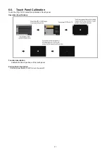


8. The LCD screen darkens when shifting to the update processing, and the
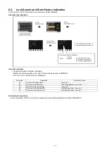
Status indicator
goes OFF. During
updating software,
Status indicator
is OFF.
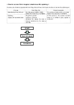
Software update takes
approx. 1 to 2min
.
Do not power down while updating.
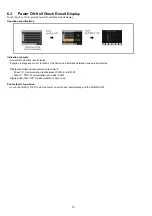
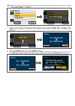
9. When the update is completed, the power automatically turns OFF / ON and the message
“Update is
completed.
”
is displayed. After the power is ON again,
Status indicator is ON.
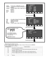
10. Select the
“OK”
button. (Touch the
“OK”
button.) The normal “Recording” mode screen is displayed.
11. Confirm that the version number is renewed for your confirmation update was correctly done follow the item
“7-2-1. Version display method”
.
The message does not display on the screen.
Update is completed.
OK
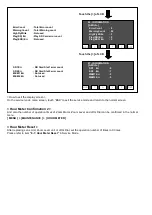
During updating software,
Status indicator
is OFF.
In updating succeed,
Status indicator
lights.
Содержание AG-AC30PJ
Страница 4: ...3 Model No AG AC30PJ PB ...
Страница 5: ...4 ...
Страница 6: ...5 ...
Страница 7: ...6 ...
Страница 8: ...7 Model No AG AC30EJ ...
Страница 9: ...8 ...
Страница 12: ...11 ...
Страница 14: ......
Страница 16: ...13 ...
Страница 17: ...14 ...
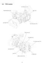
Страница 37: ...24 8 2 PCB Location ...
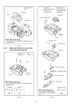
Страница 40: ...27 8 3 1 Removal of the Lens Hood Unit Lens Mask Fig D1 Fig D2 8 3 2 Removal of the Grip Ass y Fig D3 ...
Страница 41: ...28 Fig D4 8 3 3 Removal of the Zoom Lever Unit Power SS Unit Grip Unit Fig D5 Fig D6 ...
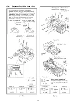
Страница 42: ...29 8 3 4 Removal of the Side Case L Unit Fig D7 Fig D8 ...
Страница 43: ...30 8 3 5 Removal of the XLR Rear P C B Unit AV Jack P C B DC Remote Jack P C B Fig D9 Fig D10 ...
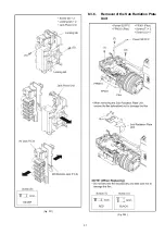
Страница 44: ...31 Fig D11 8 3 6 Removal of the Sub Radiation Plate Unit Fig D12 ...
Страница 45: ...32 8 3 7 Removal of the LED Light P C B Fig D13 8 3 8 Removal of the XLR Front Unit Fig D14 ...
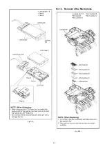
Страница 48: ...35 Fig D21 8 3 13 Removal of the Microphone Fig D22 ...
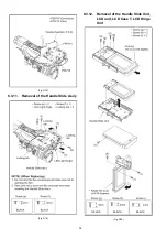
Страница 49: ...36 8 3 14 Removal of the Handle Case L Unit Fig D23 8 3 15 Removal of the ND Case Fig D24 ...
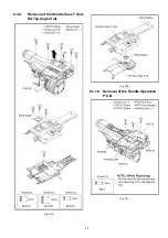
Страница 50: ...37 8 3 16 Removal of the Side Case R Ass y Fig D25 8 3 17 Removal of the Side R Operation P C B Fig D26 ...
Страница 51: ...38 8 3 18 Removal of the Dial P C B Kuru pon Unit Fig D27 8 3 19 Removal of the MF Unit Fig D28 ...
Страница 53: ...40 8 3 22 Removal of the Main P C B Fig D32 Fig D33 8 3 23 Removal of the Handle Unit Fig D34 ...
Страница 55: ...42 Fig D39 8 3 26 Removal of the Battery Catcher P C B Fig D40 ...
Страница 56: ...43 8 3 27 Removal of the Speaker Fig D41 8 3 28 Removal of the EVF Unit Fig D42 ...
Страница 57: ...44 Fig D43 ...
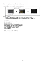
Страница 60: ...49 Level Shot Adjutment Chart ...
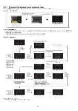
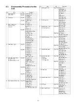
Страница 62: ...51 9 1 2 Adjustment Items Adjustment item as follows ...
Страница 65: ...54 ...
Страница 66: ...55 ...
Страница 67: ...56 ...
Страница 68: ...57 ...
Страница 69: ...58 ...
Страница 70: ...59 ...
Страница 71: ...60 ...
Страница 72: ...61 ...
Страница 85: ......
Страница 86: ......
Страница 116: ......
Страница 119: ...1 5 2 6 R L 6 5 5 1 R L 6 5 5 2 F P 6 5 5 1 D 6 5 5 1 D 6 5 5 2 M K 1 M K 2 ...
Страница 120: ......
Страница 122: ...MK1 MK2 C3901 D3901 C3902 D3902 ...
Страница 125: ...M K 3 M K 4 D 6 5 0 1 D 6 5 0 2 D 6 5 0 3 D 6 5 0 4 D 6 5 0 5 D 6 5 0 6 D 6 5 0 7 D 6 5 0 8 ...
Страница 126: ...8 7 2 5 1 CL6501 CL6502 CL6503 RL6504 RL6505 FP6501 MK1 MK2 ...
Страница 127: ...1 5 2 6 4 1 M K 1 M K 2 R L 6 9 3 6 F P 6 9 3 6 F P 6 9 3 7 ...
Страница 128: ...1 ET6931 RL6937 ...
Страница 131: ...1 4 2 3 M K 3 M K 4 J K 6 3 0 1 ...