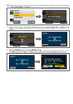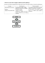
< Details about Camera Error Code >
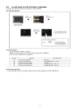
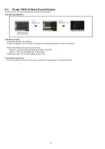
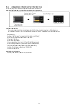
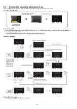
Function to display the last 3 camera error codes in the error history saved in EEPROM.
The error codes represent as follows.
ERROR CODE
Contents of Error
51
Focus lens control is abnormal
52
2
nd
Zoom stepping motor /Lens unit control is abnormal (Front side lens)
53
OIS lens control is abnormal
54
3
rd
Zoom stepping motor/Lens unit control is abnormal (Center lens)
55
4
th
Zoom stepping motor/Lens unit control is abnormal (Rear side lens)
00
No error
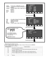
ZOOM
: Total number of ZOOM Motor operation
ZOOM. M
: The total number of times of Grip Zoom lever
operation
ZOOM. S
: The total number of times of Sub Zoom lever
operation
ND. F1
: Not used
ND. F2
: Not used
IR. F
: Not used
03 . INFORMATION
[ HourMeter ]
ZOOM
: 000808
ZOOM. M
: 000872
ZOOM. S
: 000152
ND. F1
: 000000
ND. F2
: 000000
I R. F
: 000000
BAK
SET
>
<
^
V
Touch the [>] of LCD.
04 . INFORMATION
[ HourMeter ]
P.ON
: 000551
LCD
: 000113h29m21s
EVF
: 000000h59m09s
FAN
: 000000h00m00s
JOG DIAL
: 000000
BAK
SET
>
<
^
V
P.ON
: The number of times of Power SW operation
LCD
: Operation time of LCD
EVF
: Operation time of EVF
FAN
: Not used
JOGDIAL
: The total number of times of JOG DIAL push
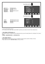
Touch the [>] of LCD.
05 . INFORMATION
[ CAM Info ]
CAM
: 00 00 00
SUB CAM
: - -
BAK
SET
>
<
^
V
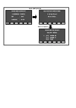
< Display of CAM Error code >
CAM : 00 00 00
A: the third to last error
B: the second to last error
C: the last error
SUB CAM : Not used
A
C
B
Touch the [>] of LCD.
Содержание AG-AC30PJ
Страница 4: ...3 Model No AG AC30PJ PB ...
Страница 5: ...4 ...
Страница 6: ...5 ...
Страница 7: ...6 ...
Страница 8: ...7 Model No AG AC30EJ ...
Страница 9: ...8 ...
Страница 12: ...11 ...
Страница 14: ......
Страница 16: ...13 ...
Страница 17: ...14 ...
Страница 37: ...24 8 2 PCB Location ...
Страница 40: ...27 8 3 1 Removal of the Lens Hood Unit Lens Mask Fig D1 Fig D2 8 3 2 Removal of the Grip Ass y Fig D3 ...
Страница 41: ...28 Fig D4 8 3 3 Removal of the Zoom Lever Unit Power SS Unit Grip Unit Fig D5 Fig D6 ...
Страница 42: ...29 8 3 4 Removal of the Side Case L Unit Fig D7 Fig D8 ...
Страница 43: ...30 8 3 5 Removal of the XLR Rear P C B Unit AV Jack P C B DC Remote Jack P C B Fig D9 Fig D10 ...
Страница 44: ...31 Fig D11 8 3 6 Removal of the Sub Radiation Plate Unit Fig D12 ...
Страница 45: ...32 8 3 7 Removal of the LED Light P C B Fig D13 8 3 8 Removal of the XLR Front Unit Fig D14 ...
Страница 48: ...35 Fig D21 8 3 13 Removal of the Microphone Fig D22 ...
Страница 49: ...36 8 3 14 Removal of the Handle Case L Unit Fig D23 8 3 15 Removal of the ND Case Fig D24 ...
Страница 50: ...37 8 3 16 Removal of the Side Case R Ass y Fig D25 8 3 17 Removal of the Side R Operation P C B Fig D26 ...
Страница 51: ...38 8 3 18 Removal of the Dial P C B Kuru pon Unit Fig D27 8 3 19 Removal of the MF Unit Fig D28 ...
Страница 53: ...40 8 3 22 Removal of the Main P C B Fig D32 Fig D33 8 3 23 Removal of the Handle Unit Fig D34 ...
Страница 55: ...42 Fig D39 8 3 26 Removal of the Battery Catcher P C B Fig D40 ...
Страница 56: ...43 8 3 27 Removal of the Speaker Fig D41 8 3 28 Removal of the EVF Unit Fig D42 ...
Страница 57: ...44 Fig D43 ...
Страница 60: ...49 Level Shot Adjutment Chart ...
Страница 62: ...51 9 1 2 Adjustment Items Adjustment item as follows ...
Страница 65: ...54 ...
Страница 66: ...55 ...
Страница 67: ...56 ...
Страница 68: ...57 ...
Страница 69: ...58 ...
Страница 70: ...59 ...
Страница 71: ...60 ...
Страница 72: ...61 ...
Страница 85: ......
Страница 86: ......
Страница 116: ......
Страница 119: ...1 5 2 6 R L 6 5 5 1 R L 6 5 5 2 F P 6 5 5 1 D 6 5 5 1 D 6 5 5 2 M K 1 M K 2 ...
Страница 120: ......
Страница 122: ...MK1 MK2 C3901 D3901 C3902 D3902 ...
Страница 125: ...M K 3 M K 4 D 6 5 0 1 D 6 5 0 2 D 6 5 0 3 D 6 5 0 4 D 6 5 0 5 D 6 5 0 6 D 6 5 0 7 D 6 5 0 8 ...
Страница 126: ...8 7 2 5 1 CL6501 CL6502 CL6503 RL6504 RL6505 FP6501 MK1 MK2 ...
Страница 127: ...1 5 2 6 4 1 M K 1 M K 2 R L 6 9 3 6 F P 6 9 3 6 F P 6 9 3 7 ...
Страница 128: ...1 ET6931 RL6937 ...
Страница 131: ...1 4 2 3 M K 3 M K 4 J K 6 3 0 1 ...

