©2016 PACE Inc., Vass, North Carolina,
All Rights Reserved
Page
20
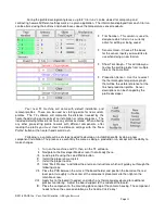
X. The BGA workstation will pick up component. If the vacuum pick fails to pick up the
component, reset the component in the nest and click retry.
XI. If Auto Flux Dip is selected, replace the component nest with the flux dip tray and follow
onscreen directions. After fluxing is complete, restore flux dip tray and component nest to
their original locations.
XII. Slide component nest out of the way, towards the back of the machine so the optics are
unobstructed.
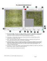
XIII. The component alignment screen will come up and the heater head will move down
towards the focal position.
XIV. Adjust the zoom and lighting as needed in order to see the pads on the PCB as well as
the solder balls or leads on the component. Then, using the theta adjustment and X/Y
micrometers, align the component to the PCB.
XV. After alignment is complete, click the Alignment Complete button to prepare for heating.
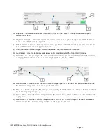
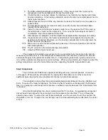
XVI. If auto placement is active, the heater head will place the component and nozzle into
position over the board. Otherwise, use the onscreen adjustments to manually lower the
heater head into final position.
XVII. Make sure any extra thermocouples being used are in the correct location and click the
Start Heating Button.
XVIII. The TF unit will run the selected temperature profile.
XIX. Allow the PCB to cool and remove.
If the component installation was successful, it is a good idea to try it once more to check for
consistency and then save it! If the component installation was not successful, examine the situation
and make changes to the profile for another trial run. Temperature graphs from up to 3 previous trial
runs will be available for comparison to current settings. When saving a profile, don’t forget to select the
primary temperature sensor for future reference when repeating the profile in production mode.
Small Components
The TF-1800 and TF-2800 are capable of working with very small components, as small as
1mm square. When working with components ranging from 5mm down to 1mm there are some
additional steps required for accurate placement during installation procedures.
The standard Centering Nest can accommodate components between the sizes of 65mm and
5mm. To work with smaller components, the Centering Nest should be exchanged with the Microchip
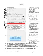
Nest. An in-program walk through of this process is added to a profile whenever the “Align Holder” box
is checked.
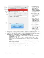
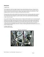
Once the Microchip Nest has been installed onto the TF machine , the appropriate component
slot will need to be aligned to the vacuum pick so the component can be lifted. This is achieved by
adjusting two screws. To adjust the nest forward and back, use the screw on the left that controls the
stop block on the rail. To adjust the nest left/right, use the screw protruding from underneath the center
of nest.

