CDV Construction Manual – Issue 3
Page 5
1.2
CDV
SPECIFICATIONS
1.
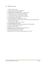
PCB size: 52mm x 32mm.
2.
Controls: Rotary encoder and 2 pushbuttons.
3.
Display: 0.96 inch monochrome OLED.
4.
Signal outputs: 1 x fixed frequency, 1 x variable frequency.
5.
Fixed output frequency range: 100KHz to 100MHz.
6.
Variable output frequency range: 100KHz to 100MHz.
7.
Scan mode ranges: +-5KHz, +-50KHz of start frequency.
8.
IF offset: VFO > IF, VFO < IF, NONE.
9.
Receiver incremental Tuning (RIT) range: no limit.
10.
Programmable frequency steps: Select from the range 1Hz, 10Hz, 100Hz, 1KHz, 5Khz,
10KHz, 25KHz and 100KHz.
11.
Operating supply voltage range: 5 to 15V DC.
12.
Average operating current: 35mA.
13.
TX/RX and USB/LSB logic inputs. An input larger than 3.3V is logic high.
14.
Low power supply alarm: 5 to 15V DC.
15.
Output impedance: 50 Ohms.
16.
Output drive level: over 3V pk-pk Hi Z. 2V pk-pk 50 ohms.
17.
Output coupling: series capacitor (100nF).
18.
Reverse polarity protection: series diode.
19.
Input Output connectors: JST 2mm pin pitch polarised connectors.
Содержание CDV
Страница 1: ...CDV Construction Manual Issue 3 Page 1 CDV COMPACT DIGITAL VFO CONSTRUCTION MANUAL ...
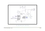
Страница 8: ...CDV Construction Manual Issue 3 Page 8 Figure 1 Microcontroller and power supply schematic ...
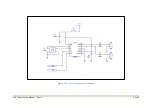
Страница 9: ...CDV Construction Manual Issue 3 Page 9 Figure 2 Si5351A Clock generator schematic ...
Страница 10: ...CDV Construction Manual Issue 3 Page 10 Figure 3 Display and controls schematic ...
Страница 30: ...CDV Construction Manual Issue 3 Page 30 Figure 11 Attenuator filter board fitted to the CDV ...


