CDV Construction Manual – Issue 3
Page 28
12.3
C
ONSTRUCTION
12.3.1
S
OLDERING
SMD
DEVICES
The resistors, capacitors and inductors are surface mount (SMD) components. Normally they
are difficult to work with, but in this kit larger package types have been specified to make it
easier to build. Below is a suggested list of tools to satisfactorily complete construction:
a.
thin solder
b.
small tipped soldering iron
c.
illuminated magnifier
d.
fine tweezers
Melt a small spot of solder onto one of the component PCB pads. Pick up the SMD component by
the sides with tweezers and place onto the pads. While holding the component steady place the
tip of the soldering iron on the pad with the spot of solder to melt it again. Remove the iron and
let things cool and settle. Check the positioning of the component and if not in the correct spot,
melt the solder and move gently with tweezers. Once the component is located solder the other
end using as little solder as possible. Then go back to the first pad and apply a little more solder
to ensure the joint is secure. Inspect the job under a magnifier looking for solder bridges and
dry joints.
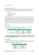
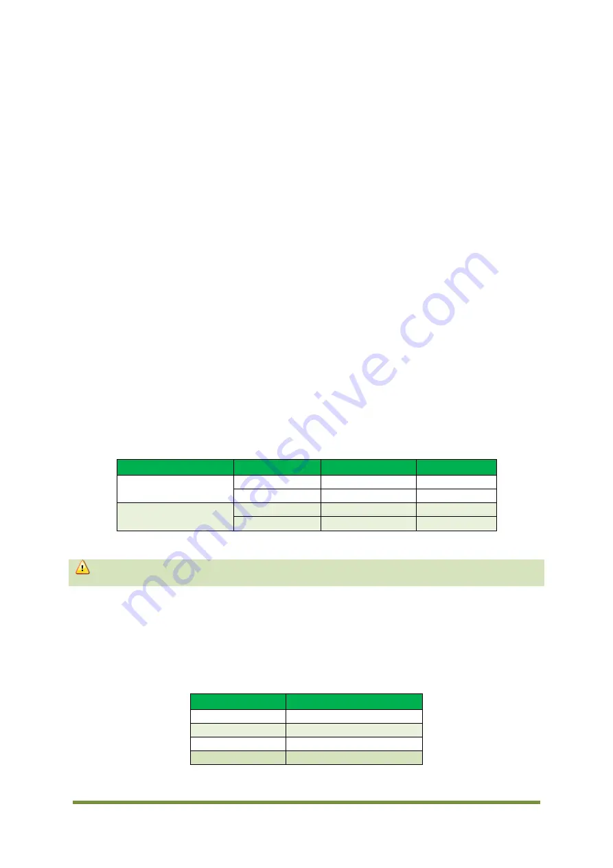
Step 1: Resistors
Locate and install the three SMD resistors. R1 and R3 have the same value, while R2 has a
different value. Use the table below to identify the correct values.
Attenuation
Resistor
Resistor label
Value
6dB
R1, R3
1500
150 ohms
R2
39R0
39 ohms
12dB
R1, R3
82R0
82 ohms
R2
91R0
91 ohms
Step 2: Capacitors
Locate and install the two SMD capacitors. The capacitors have the same value so they can go in
either position. In general SMD ceramic capacitors do not have markings, so the values can only
be read with a capacitance meter and miniature probes.
Filter
Value
10MHz
470pF
20MHz
220pF
30MHz
150pF
40MHz
120pF
If only the low pass filter is required and no attenuation, then omit the resistors and
install a solder bridge across R2.
Содержание CDV
Страница 1: ...CDV Construction Manual Issue 3 Page 1 CDV COMPACT DIGITAL VFO CONSTRUCTION MANUAL ...
Страница 8: ...CDV Construction Manual Issue 3 Page 8 Figure 1 Microcontroller and power supply schematic ...
Страница 9: ...CDV Construction Manual Issue 3 Page 9 Figure 2 Si5351A Clock generator schematic ...
Страница 10: ...CDV Construction Manual Issue 3 Page 10 Figure 3 Display and controls schematic ...
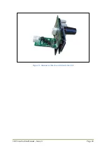
Страница 30: ...CDV Construction Manual Issue 3 Page 30 Figure 11 Attenuator filter board fitted to the CDV ...

