RT1003 Manual
Revision:
190628
41
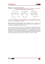
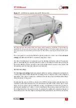
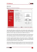
Figure 17.
An INS device mounted on our RT-Strut system
The image shows an INS (with its IMU axes clearly visible) mounted on an RT-Strut. It the RT-Strut was
mounted in the vehicle as shown, the settings on the Orientation page of NAVconfig would need to be set to Y-
axis (green) points Left; Z-axis (blue) points forward. The INS will then convert measurements into the vehicle
frame.
If it is not possible to mount the RT1003 squarely within the vehicle, select
Use advanced
settings
and define the RT1003’s orientation using these values.
For correct initialisation it is necessary to get the heading orientation correct. The product
gets its initial heading by assuming that the vehicle is travelling forwards and in a straight
line. If the definition of the vehicle's X-axis (forward direction) is incorrect, the system will
not initialise correctly when the vehicle moves forwards.
Get improved settings
The
Get improved settings
button provides the ability to read the configuration settings from
a warmed up system. While the RT1003 is running it tries to improve some of its configured
parameters. This option is useful if a calibration run has been done and the Kalman filter's
values are known to be good.
In particular the system will try to improve the GNSS antenna position measurements, the
orientation of the dual antennas, the yaw orientation of the INS in the vehicle and, if one is
being used, the wheel speed calibration values. In applications where the product is
permanently installed in a vehicle, it can be beneficial to import these improved values into
the configuration file to be used next time. It can make the results more consistent. Figure 18
shows this process. The Get improved settings feature should not be used if there is a risk the
Содержание RT1003
Страница 1: ...Confidently Accurately User Manual RT1003 GNSS aided inertial navigation system ...
Страница 108: ...Confidential Information Oxford Technical Solutions ...
Страница 110: ......

